Optically multiplexed imaging system and methods of operation

a technology of optical data collection and multiplexing, applied in the direction of spectral investigation, instruments, electrical equipment, etc., can solve the problems of insufficient utilization of focal plane rows insufficient utilization of pushbroom imaging spectrometers, and insufficient utilization of focal plane rows used for spectral dimension, etc., to achieve efficient utilization and improve the efficiency of optical data collection

Active Publication Date: 2011-02-08
ITRES RES
View PDF24 Cites 25 Cited by
  • Summary
  • Abstract
  • Description
  • Claims
  • Application Information

AI Technical Summary

Benefits of technology

[0028]In accordance with the invention, there is provided an optical multiplexer system enabling improvement in the efficiency of optical data collection by creating multiple fields-of-view at the focal plane array (a “virtual” focal plane array). This virtual focal plane array enables imaging of an increased number of pixels in the across-track dimension (or other dimensions) by efficient utilization of one or more physical focal plane sensor arrays.
[0029]This increased number of across-track pixels can be used to improve the spatial resolution of the image, increase the swath width, provide various combinations of improved spatial resolution and increased swath width or provide other functionalities arising from differing fields-of-view, or multiple imaging of the same field-of-view.
[0030]In one embodiment, if the multiple fields-of-view images are of approximately the same area (even if not at the same time or the same viewing angle), the system in accordance with the invention can provide other functionalities arising from multiple looks of the same area including improved stereo imaging or other advantages such as different spectral ranges or adaptability to differing light conditions.
[0031]In other embodiments, using beam deflection principles, the invention provides systems that can be used for panchromatic or broad-band imagers to provide an increased number of across-track pixels when used with one or more focal plane sensor arrays.
[0032]Accordingly, in one embodiment, the invention provides an optical multiplexer for increasing optical data collection efficiency received simultaneously across two or more fields of view comprising: a first optical path for operatively receiving optical data from a first field of view; a second optical path having a second optical path beam deflection system for operatively receiving optical data from a second field of view, the first optical path and second optical path beam deflection system for directing the optical data from the first and second fields of view through a common optical train, the optical train for focusing the optical data passing through the optical train onto different sections of one or more focal plane arrays.
[0044]In another embodiment, the optical train includes an aperture that is restricted in one dimension to reduce the separation distance of at least one optical path of a corresponding optical path beam deflection system from the focal plane array while minimizing degradation in sensitivity and signal to noise ratio.

Problems solved by technology

Thus, the number of across-track pixels available from pushbroom imagers is often limited by the pixel arrangement of commercially available focal plane sensor arrays.
Thus current designs for push-broom imaging spectrometers can under-utilize the focal plane rows (used for the spectral dimension) and lack the desired number of columns (for the across-track spatial dimension).
However, specialized custom sensor arrays can only be produced at very high costs that tend to defeat the objectives of providing commercially viable pushbroom imaging instruments and in addition there are often practical constraints as to the maximum dimension of an array due to fabrication limitations.
The net result of this “standard” focal plane geometry is that the desired spatial resolution may be compromised.
Compromised spatial resolution will, as a result, increase the required number of separate passes over the scene of interest that are needed to cover an area due to the limited swath width.
An increase in the number of passes increases the time and cost to acquire such imagery.
Moreover, even if focal plane arrays with large numbers of spatial pixels were available, the standard design would lead to the need for increased dimensions of the optical components to accommodate the larger image dimension, resulting in substantially greater size and costs of the optics.
Similarly, the same problem arises with non-spectrographic pushbroom imagers.
However, better sensor availability does not address the problem of the concomitant need for larger optical elements to accommodate these long linear arrays.
A review of the prior art reveals that past systems have not provided an effective solution to the above problems.
In addition, this system does not spread the separate fields of view across a single or multiple detectors but rather employs a single dual-wavelength detector.

Method used


Image

  • Optically multiplexed imaging system and methods of operation
  • Optically multiplexed imaging system and methods of operation
  • Optically multiplexed imaging system and methods of operation

Examples


Embodiment Construction

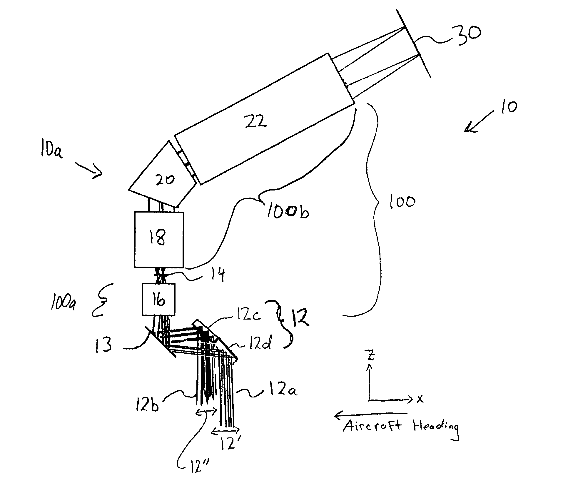
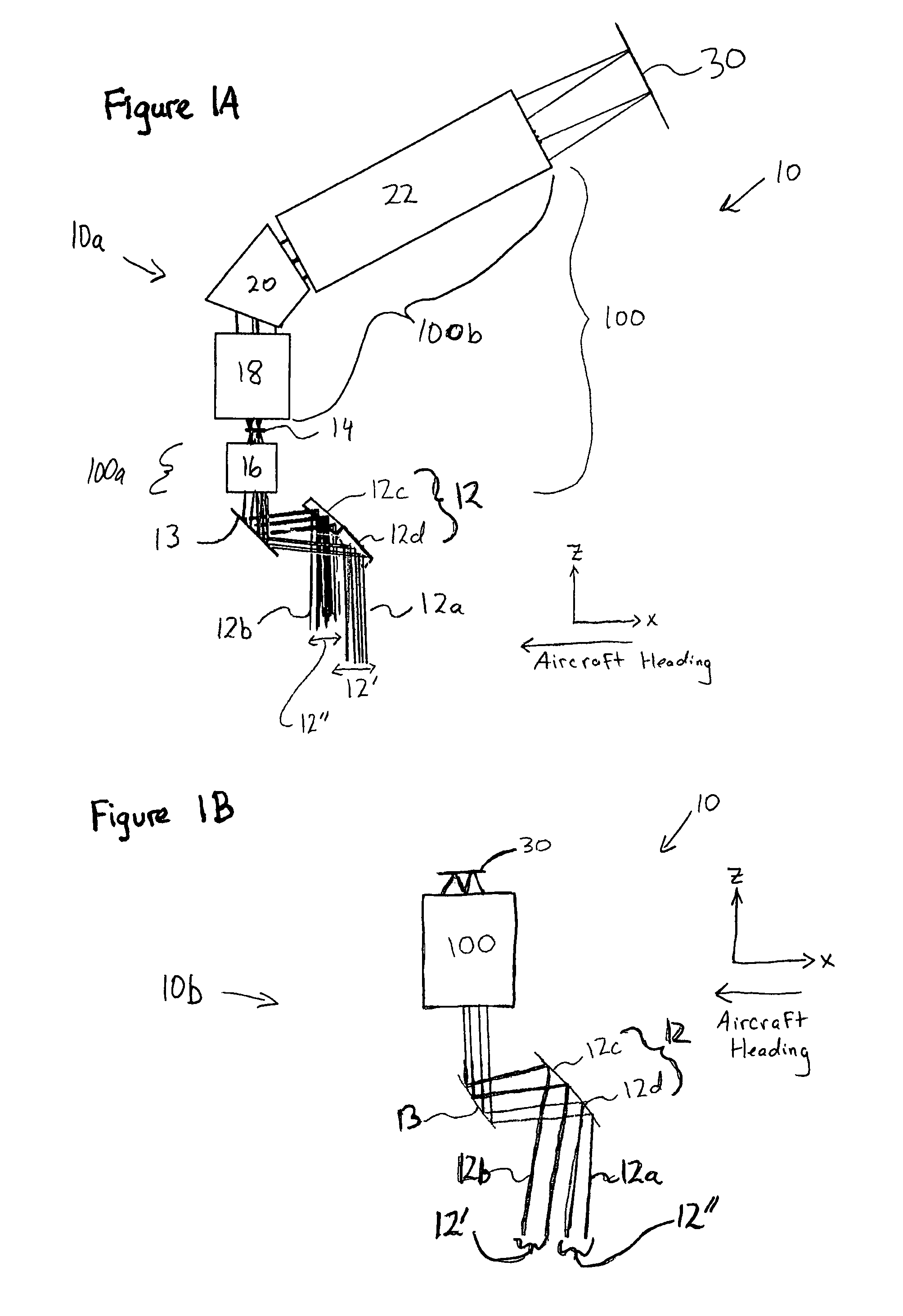
[0057]In accordance with the invention and with reference to the figures, embodiments of an optical multiplexer 10 are described.

[0058]Generally, the optical multiplexer 10 includes a first optical path 12a for operatively receiving optical data from a first field of view 12′ and at least one beam deflection system 12c for operatively receiving optical data from at least a second field of view 12″ (FIG. 1B). The first and second fields of view (FOVs) may be identical and more than two FOVs may be imaged. The first optical path and at least one beam deflection system direct the optical data from the first 12′ and at least second 12″ fields of view through an optical train 100, the optical train for focusing the optical data passing through the optical train 100 onto adjacent sections of a focal plane array 30. In different embodiments, the focal plane array 30 may be a single sensor array or be comprised of separate sensor arrays that may be of a similar type or be different from one...


PUM


Abstract

The invention describes an optical multiplexer for increasing optical data collection efficiency across at least two fields of view. The optical multiplexer includes a first optical path for operatively receiving optical data from a first field of view and at least one beam deflection system for operatively receiving optical data from at least a second field of view. The optical multiplexer also includes an optical train for focusing the optical data passing through the optical train onto adjacent sections of a focal plane array. The invention provides improvements including expanded across-track swaths, higher spatial resolution, imaging of real-time references on every frame, coincident imaging along separate paths, stereo imaging and other increases in imaging functionality.

Description

RELATED APPLICATIONS[0001]This application claims the benefit of priority from U.S. application 60 / 743,338 filed Feb. 22, 2006.FIELD OF THE INVENTION[0002]The invention describes an, optical multiplexer for increasing optical data collection efficiency across at least two fields of view. The optical multiplexer includes a first optical path for operatively receiving optical data from a first field of view and at least one beam deflection system for operatively receiving optical data from at least a second field of view. The optical multiplexer also includes an optical train for focusing the optical data from the above optical paths onto adjacent sections of a focal plane sensor array. In various embodiments, the invention enables expanded across-track swaths, higher spatial resolution, imaging of real-time references on every frame, coincident imaging along separate paths, stereo imaging and other improvements in imaging functionality.BACKGROUND OF THE INVENTION[0003]Different image...

Claims


Application Information

Patent Timeline
Patent Type & Authority Patents(United States)
IPC IPC(8): G01J3/28G02B30/60
CPCG01J3/02G01J3/021G01J3/0294G01J3/04G03B15/006G02B27/1066G02B27/14G01J3/2823G02B23/12
Inventor ACHAL, STEPHENANGER, CLIFFORD
Owner ITRES RES
Why Eureka
Try Eureka