Method and apparatus for mating irregular or non-circular exhaust ports with tubing of a circular cross section in exhaust flange assemblies

a technology of exhaust flanges and circular cross sections, which is applied in the direction of branching pipes, machines/engines, other domestic objects, etc., can solve the problems of many unrealized advantages, and achieve the effect of reducing cycle time and efficiently fabricated

Inactive Publication Date: 2011-02-15
CAR SOUND EXHAUST SYST
View PDF18 Cites 8 Cited by
  • Summary
  • Abstract
  • Description
  • Claims
  • Application Information

AI Technical Summary

Benefits of technology

[0008]The present disclosure describes an improved exhaust flange assembly for efficiently, economically, and robustly mating exhaust tubing of a circular cross-section to irregular or non-circular exhaust ports involving a flange adapted to accommodate the geometric shape of both the exhaust port and the mating terminus of the headpipe.
[0011]This unique design allows each headpipe to be inserted into a corresponding counterbore and welded into place with little or no custom tooling or skilled manual labor. The counterbored flange provides lateral support to the headpipe-flange coupling; therefore, the weld will realize very little lateral stress greatly increasing the strength and durability of the union.
[0013]To accommodate exhaust ports with a cross-sectional dimension greater than the standard inner diameter of exhaust tubing, the headpipe influent may be flared to increase its inner diameter. While flaring the headpipe influent is an additional manufacturing step, it can be performed in a uniform manner by automated or semi-automated tools, with an efficiency far greater than manually custom shaping the mating terminus of each headpipe. Flaring can also be done without risk of unwanted creases or sharp bends that often accompany custom shaping methods. The disclosed exhaust flange coupling allows headpipes to be prefabricated as off-the-shelf component parts with little or no customization required during assembly.
[0018]Another objective is to provide an innovative headpipe-flange coupling for exhaust flange assemblies designed to accommodate irregular or non-circular exhaust ports that are capable of being of fabricated efficiently, reducing cycle time by realizing the advantages of CNC manufacturing.
[0019]A further objective is to provide an effective method and apparatus for coupling irregular or non-circular exhaust ports to standard exhaust tubing of a circular cross-section in a robust manner.
[0020]A still further objective is to provide a method and apparatus of joining standard exhaust tubing to irregular or nonstandard exhaust ports while reducing cost related to scrap, custom tooling, training, and skilled manual labor.

Problems solved by technology

The flange of the presently disclosed exhaust flange assembly shares some basic similarities with flanges that are known in the art; however, it also contains an innovative coupling that yields many unrealized advantages.

Method used


Image

  • Method and apparatus for mating irregular or non-circular exhaust ports with tubing of a circular cross section in exhaust flange assemblies
  • Method and apparatus for mating irregular or non-circular exhaust ports with tubing of a circular cross section in exhaust flange assemblies
  • Method and apparatus for mating irregular or non-circular exhaust ports with tubing of a circular cross section in exhaust flange assemblies

Examples


Embodiment Construction

[0029]The above described drawing figures illustrate an exemplary embodiment of the joint apparatus and its method of use in at least one of its preferred, best mode embodiments, which is further defined in detail in the following description. Those having ordinary skill in the art may be able to make alterations and modifications to what is described herein without departing from its spirit and scope of the disclosure. Therefore, it must be understood that what is illustrated is set forth only for the purposes of example and that it should not be taken as a limitation in the scope of the present apparatus and method of use.

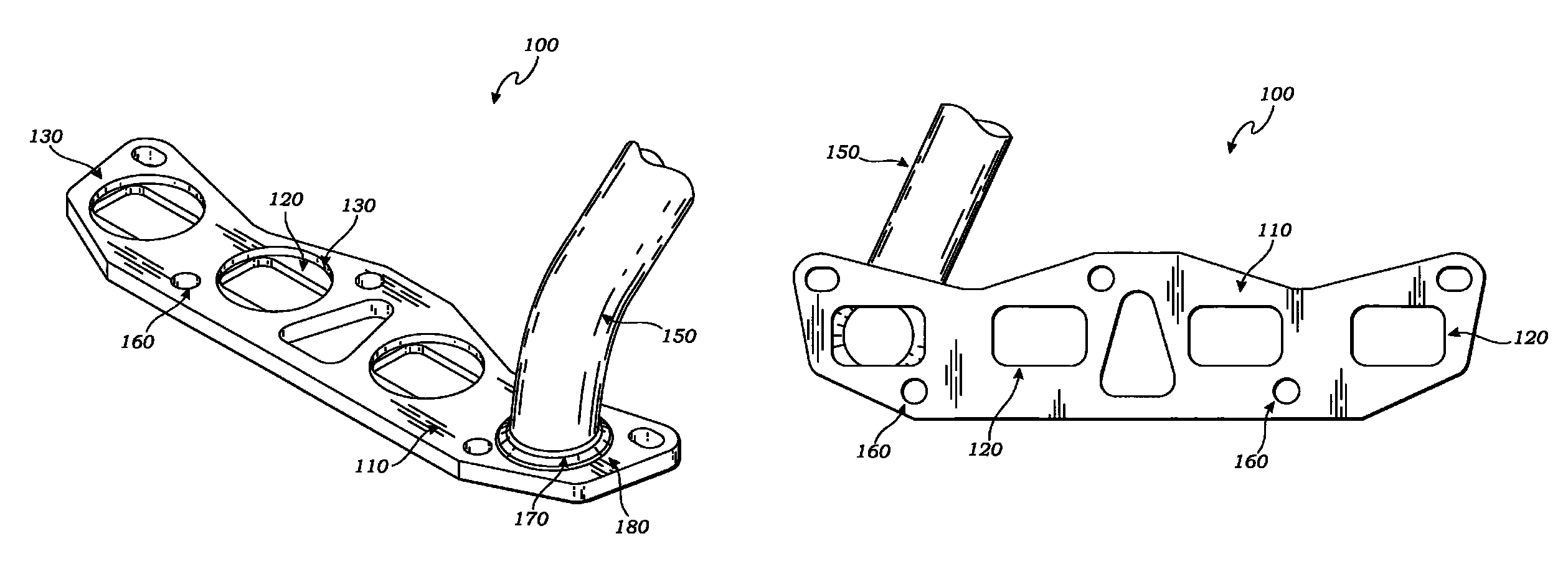
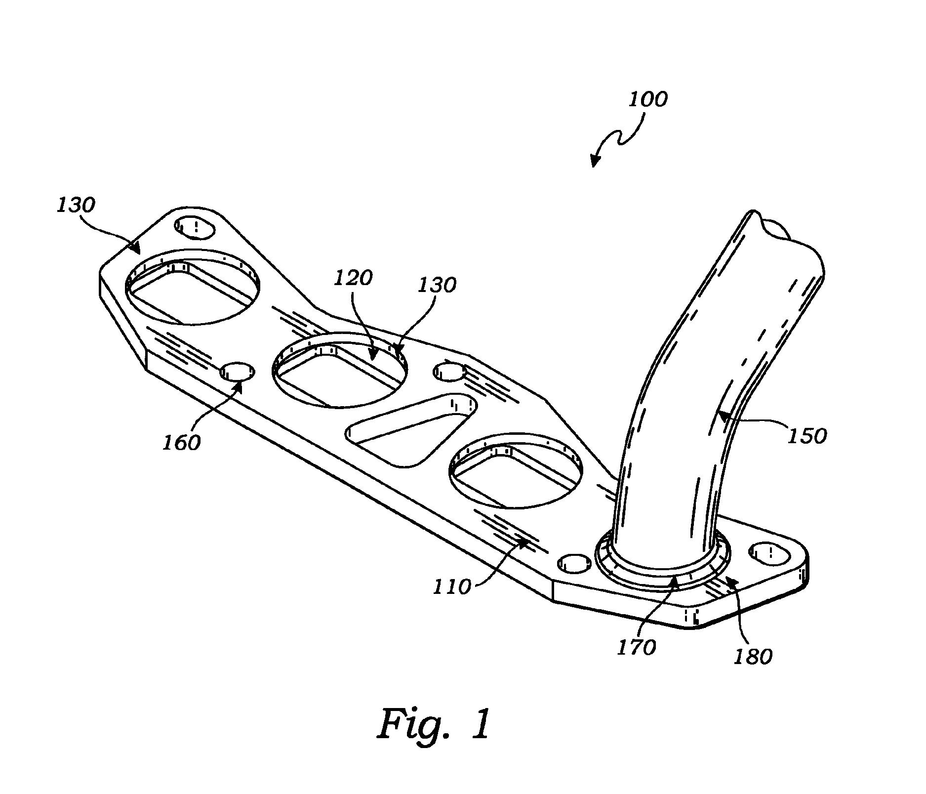
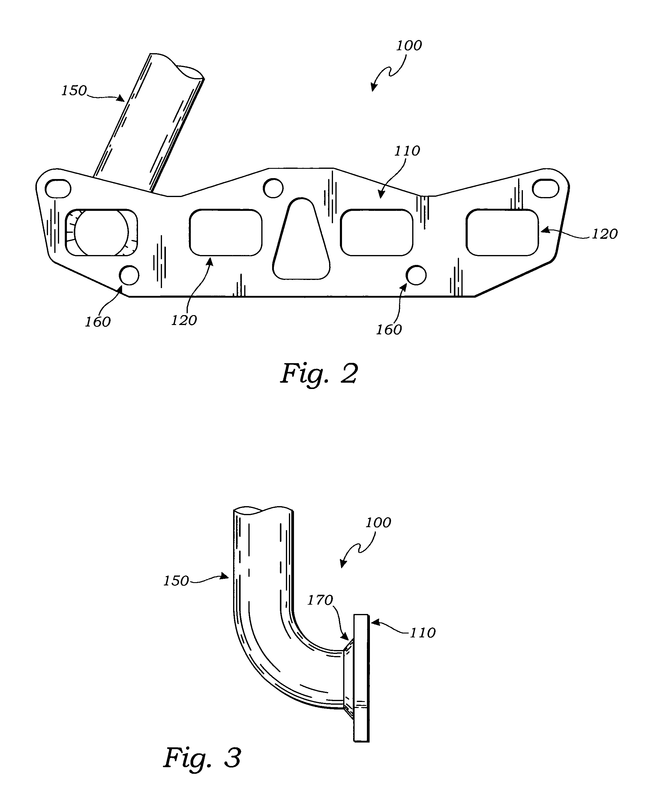
[0030]Described now in detail is an apparatus and method of efficiently, economically, and robustly mating exhaust tubing of a circular-cross section to irregular or non-circular exhaust ports. FIG. 1 is a perspective view of a partially assembled exemplary exhaust flange assembly 100. This figure depicts a plurality of flange apertures 120 similarly spaced and o...


PUM

PropertyMeasurementUnit
shapeaaaaaaaaaa
sizeaaaaaaaaaa
lengthaaaaaaaaaa

Abstract

An apparatus and method of coupling standard exhaust tubing of a circular cross-section with irregular or non-circular exhaust ports of an internal combustion engine in an efficient, economic, and robust manner. The nature of the connection allows for irregular or non-circular exhaust ports to be mated to round tubing with minimal air flow impact and a high strength welded connection, with reduced manufacturing scrap and increased CNC manufacturing capability.

Description

FIELD OF THE PRESENT DISCLOSURE[0001]This disclosure relates generally to exhaust flange assemblies, and more particularly to a coupling in exhaust flange assemblies for mating irregular or non-circular exhaust port openings to exhaust tubing of a circular cross-section in an efficient, robust, and economical manner.BACKGROUND OF THE RELATED ART[0002]Exhaust flange assemblies are typically designed to accept exhaust from single and multiple cylinders of an internal combustion engine and deliver it to an exhaust pipe. Exhaust flange assemblies include a series of headpipes aligned to collect exhaust discharge directly from each cylinder head's exhaust port. The series of headpipes typically converge at the end opposing the exhaust ports to form one tube, sometimes referred to as a collector.[0003]Exhaust flange assemblies are commonly affixed to the cylinder heads of an internal combustion engine via bolts through the flange component of the assembly. The flange is typically designed...

Claims


Application Information

Patent Timeline
Patent Type & Authority Patents(United States)
IPC IPC(8): F16L39/00
CPCF01N13/18F01N13/1805Y10T29/49398
Inventor PAOLONE, GENNARO
Owner CAR SOUND EXHAUST SYST
Why Eureka
Try Eureka