Wireless patient monitoring system

a patient monitoring and wireless technology, applied in the field of wireless patient monitoring system, can solve the problems of affecting the operation of the sensor, affecting the patient's comfort, so as to prevent interference from outside sources, reduce power consumption, and prolong the life of the power supply.

Active Publication Date: 2011-02-15
INTEGRA LIFESCI
View PDF18 Cites 318 Cited by
  • Summary
  • Abstract
  • Description
  • Claims
  • Application Information

AI Technical Summary

Benefits of technology

[0012]In a further embodiment, the sensor data can be compressed prior to transmitting the sensor data and then it can be decompressed prior to the displaying the sensor data. Compressing the sensor data can assist in shorting the second period of time and thus shortening the burst period and the lag time.
[0014]In one embodiment, the receiver is located within 15 feet of the transmitter. The proximity of the receiver to the transmitter can prolong the life of power supply because less power is needed if the transmission is over a short distance. Also, the proximity prevents dropped signals and interference from outside sources.
[0015]In another embodiment, the sensor data can be encrypted before it is transmitted wirelessly to prevent unauthorized access or tampering with the sensor data. In a further embodiment, one or both of the unique sensing device ID and the transmitter ID can be used as base keys for encrypting the data. The IDs can be used as a public key and thus either every sensing device's or transmitter's sensor data can be uniquely encrypted.

Problems solved by technology

The wires, especially leading to implanted sensors, cause difficulty for caregivers to move and treat the patient, both in and out of bed.
However, continuous wireless data transmission draws a significant amount of power.
Since the sensors are wireless, they must rely on battery power and the continuous wireless transmission shortens the battery life and thus the operational life of the sensor.
Continuous data sampling would defeat Ko's pulse power scheme, as the sensors and transmitter can never power down.
Further, Penn discloses an embodiment of providing a power supply for the system but, as Ericson does, Penn takes and stores the sensor data but does not disclose powering down the transmitter to conserve energy.
Further, Penn does not disclose how to compensate for the lag between when the sensor data is taken and when it is transmitted.

Method used


Image

  • Wireless patient monitoring system
  • Wireless patient monitoring system
  • Wireless patient monitoring system

Examples


Embodiment Construction

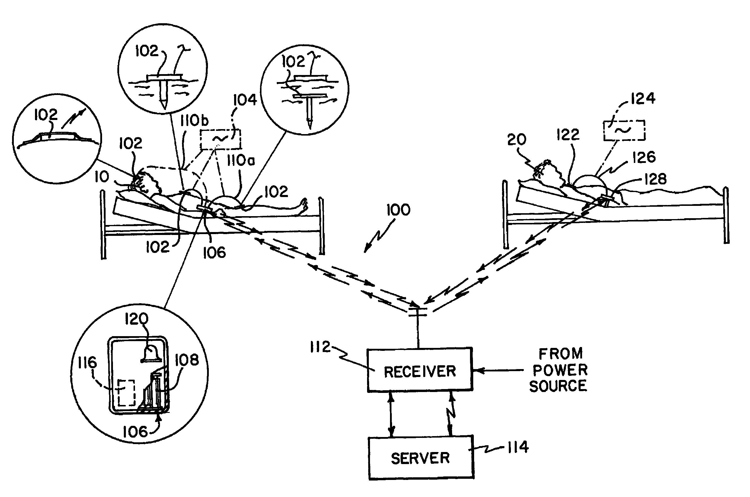
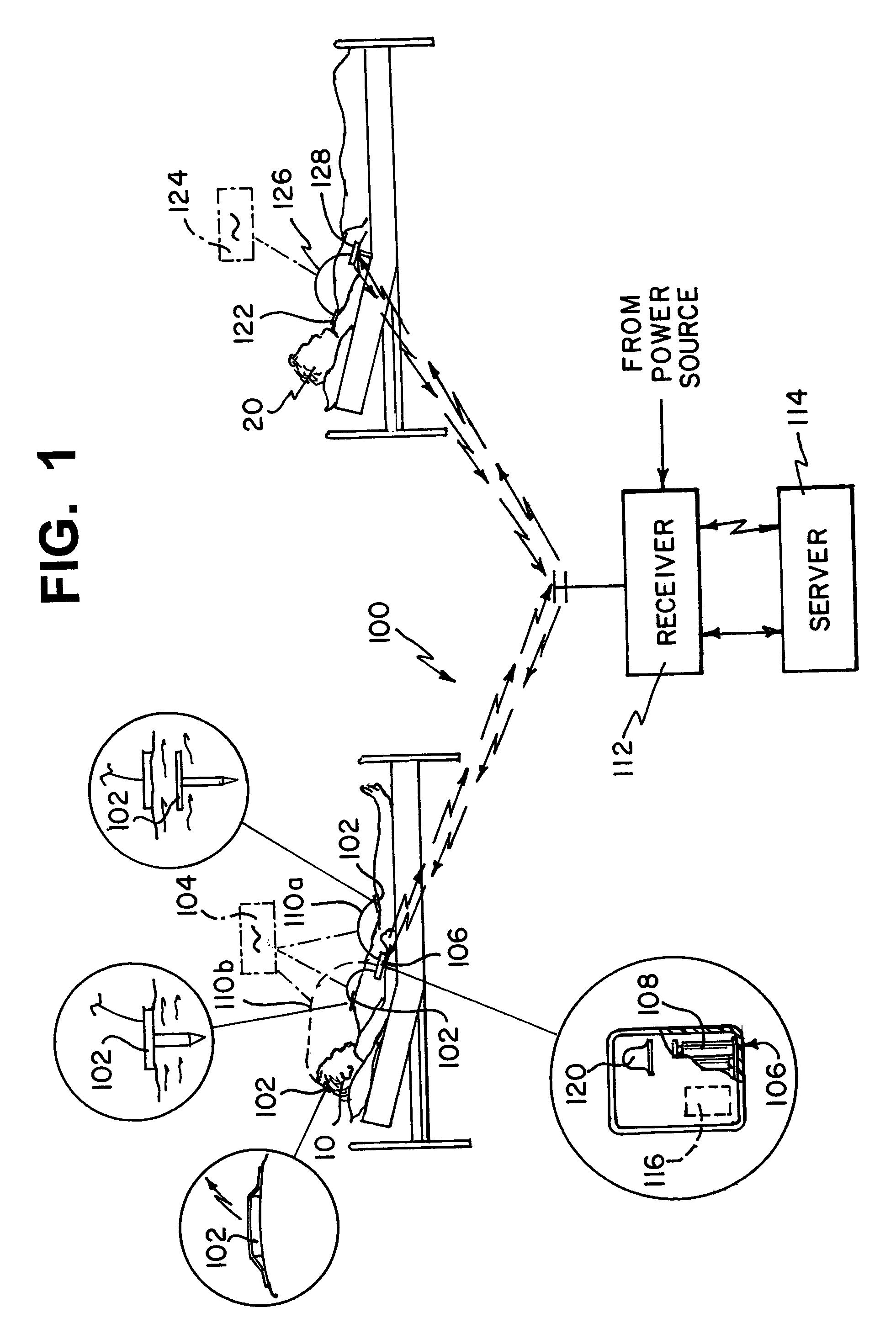
[0022]Referring to FIG. 1, a system 100 for monitoring a patient sensor is illustrated. The system 100 includes a sensing device 102 disposed on the surface of or implanted in the patient 10 that takes sensor data 104. The sensing device can be disposed or implanted anywhere on the patient 10, including implanted in the patient's brain. Sensing device 102 can be any medical sensing device, including a pressure sensor, an oxygen sensor, neural impulse sensor, temperature sensor, pH sensor, an electroencephalogram and a fetal heart monitor. The sensing device 102 can collect sensor data 104 over many different time periods. Sensor data 104 can be collected continuously, over either a predetermined or random interval, or upon a command issued from a caregiver. Sensing device 102 can be powered internally by, for example, disposable batteries, rechargeable batteries, or a capacitive device capable of storing energy transmitted through an inductive power coupling or directly through the ...


PUM


Abstract

A device and method for monitoring a patient having a sensing device taking sensor data continuously and a transmitter located on the patient and internally powered. The transmitter is normally in a power-down state and powered-up for transmitting the sensor data. A receiver is located remote from the patient and receives the sensor data transmitted wirelessly from the transmitter. The transmission is typically a burst and can also be initiated on a command. For the burst, the sensor data is accumulated over a first period. The transmitter can transmit the sensor data over a second period of time. The second period of time is shorter than the first period of time. Once the transmission is complete, transmitter can be powered down. A further step displays the sensor data at the receiver in pseudo real-time. The display is shifted by a sum of the first and the second period of time.

Description

BACKGROUND OF THE INVENTION[0001]1. Field of the Invention[0002]This invention relates to a system and method for measuring, storing and communicating sensor readings from a patient to a central system for display and analysis.[0003]2. Discussion of the Related Art[0004]For certain medical conditions, such as head trauma, it is necessary to place sensors on and in a patient to take continuous sensor readings. One shortcoming of the prior art is the need to wire the sensors to receiving and recording units located near the patient. The wires, especially leading to implanted sensors, cause difficulty for caregivers to move and treat the patient, both in and out of bed. In response, wireless sensor systems were developed that record the sensor data and do not tether the patient to wired receivers. The sensor data is transmitted wirelessly to the receiver. However, continuous wireless data transmission draws a significant amount of power. Since the sensors are wireless, they must rely o...

Claims


Application Information

Patent Timeline
Patent Type & Authority Patents(United States)
IPC IPC(8): G08B1/08
CPCA61B5/0002A61B5/0031A61B5/7232
Inventor FIFOLT, DOUGLAS A.ROSENBERG, MIKI
Owner INTEGRA LIFESCI
Why Eureka
Try Eureka