Expandable transluminal sheath

a transluminal sheath and expandable technology, applied in the field of medical devices, can solve the problems of affecting the function of the urinary tract of mammals, affecting the function of the urinary tract, and leaking of the lumen or cavity contents into the surrounding space,

Active Publication Date: 2011-02-22
ONSET MEDICAL CORP
View PDF228 Cites 78 Cited by
  • Summary
  • Abstract
  • Description
  • Claims
  • Application Information

AI Technical Summary

Benefits of technology

[0011]A need therefore remains for improved access technology, which allows a device to be transluminally passed through a relatively small diameter duct, while accommodating the introduction of relatively large diameter instruments. It would be beneficial if a urologist did not need to inventory and use a range of catheter diameters. It would be far more useful if one catheter diameter could fit the majority of patients. Ideally, the catheter would be able to enter a vessel or body lumen with a diameter of 6 to 10 French or smaller, and be able to pass instruments through a central lumen that was 12 to 18 French. These requirements appear to be contradictory but can be resolved by an embodiment of the invention described herein. Advantageously the sheath would also be maximally visible under fluoroscopy and would be relatively inexpensive to manufacture. The sheath or catheter would preferably be kink resistant and minimize abrasion and damage to instrumentation being passed therethrough. Preferably, the sheath or catheter would further minimize the potential for injury to body lumen or cavity walls or surrounding structures. Such damage could potentially lead to strictures, leakage of body lumen or cavity contents into surrounding spaces, contamination, hemorrhage, or the like.
[0014]In another embodiment of the invention, a transluminal access sheath assembly for providing minimally invasive access comprises an elongate tubular member having a proximal end and a distal end and defines a working inner lumen. In this embodiment, the tubular member comprises a folded or creased sheath that is expanded by a dilatation balloon. The dilatation balloon, can be filled with fluids at appropriate pressure, to generate the force to expand the sheath. The dilatation balloon is preferably removable to permit subsequent instrument passage through the sheath. In some embodiments, longitudinal runners may be disposed within the sheath to serve as tracks for instrumentation, which further minimize friction while minimizing the risk of catching the instrument on the expandable plastic tubular member. Such longitudinal runners are preferably circumferentially affixed within the sheath so as not to shift out of alignment. In yet another embodiment, the longitudinal runners may be replaced by longitudinally oriented ridges and valleys, termed flutes. The flutes, or runners, can be oriented along the longitudinal axis of the sheath, or they can be oriented in a spiral, or rifled, fashion.
[0016]In certain embodiments of the invention, it is beneficial that the sheath comprise a radiopaque marker or markers. The radiopaque markers may be affixed to the non-expandable portion or they may be affixed to the expandable portion. Markers affixed to the radially expandable portion preferably do not restrain the sheath or catheter from radial expansion or collapse. Markers affixed to the non-expandable portion, such as the catheter shaft of a balloon dilator may be simple rings that are not radially expandable. Radiopaque markers include shapes fabricated from malleable material such as gold, platinum, tantalum, platinum iridium, and the like. Radiopacity can also be increased by vapor deposition coating or plating metal parts of the catheter with metals or alloys of gold, platinum, tantalum, platinum-iridium, and the like. Expandable markers may be fabricated as undulated or wavy rings, bendable wire wound circumferentially around the sheath, or other structures such as are found commonly on stents, grafts or catheters used for endovascular access in the body. Expandable structures may also include dots or other incomplete surround shapes affixed to the surface of a sleeve or other expandable shape. Non-expandable structures include circular rings or other structures that completely surround the catheter circumferentially and are strong enough to resist expansion. In another embodiment, the polymeric materials of the catheter or sheath, including those of the sheath composite wall, may be loaded with radiopaque filler materials such as, but not limited to, bismuth salts, or barium salts, or the like, at percentages ranging from 1% to 50% by weight in order to increase radiopacity.
[0018]In another embodiment, the distal end of the catheter is fabricated using an inner tubular layer, which is thin and lubricious. This inner layer is fabricated from materials such as, but not limited to, FEP, PTFE, polyamide, polyethylene, polypropylene, Pebax, Hytrel, and the like. Radiopaque filler materials can be added to the polymer inner layer during extrusion to enhance visibility under fluoroscopy. The reinforcement layer comprises a coil, braid, stent, or plurality of expandable, foldable, or collapsible rings, which are generally malleable and maintain their shape once deformed. Preferred materials for fabricating the reinforcement layer include but are not limited to, stainless steel, tantalum, gold, platinum, platinum-iridium, titanium, nitinol, and the like. The materials are preferably fully annealed or, in the case of nitinol, fully martensitic. The outer layer is fabricated from materials such as, but not limited to, FEP, PTFE, polyamide, polyethylene, polypropylene, polyurethane, Pebax, Hytrel, and the like. The inner layer is fused or bonded to the outer layer through holes in the reinforcement layer to create a composite unitary structure. The structure is crimped radially inward to a reduced cross-sectional area. A balloon dilator is inserted into the structure before crimping or after an initial crimping and before a final sheath crimping. The balloon dilator is capable of forced expansion of the reinforcement layer, which provides sufficient strength necessary to overcome any forces imparted by the polymeric tubing.

Problems solved by technology

Such damage could potentially lead to strictures, leakage of body lumen or cavity contents into surrounding spaces, contamination, hemorrhage, or the like.

Method used


Image

  • Expandable transluminal sheath
  • Expandable transluminal sheath
  • Expandable transluminal sheath

Examples


Embodiment Construction

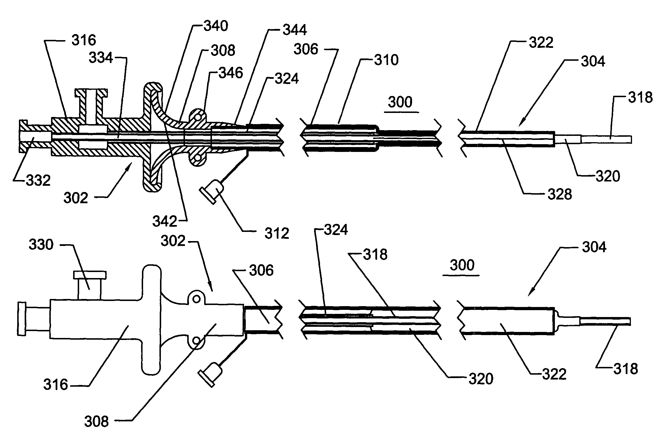
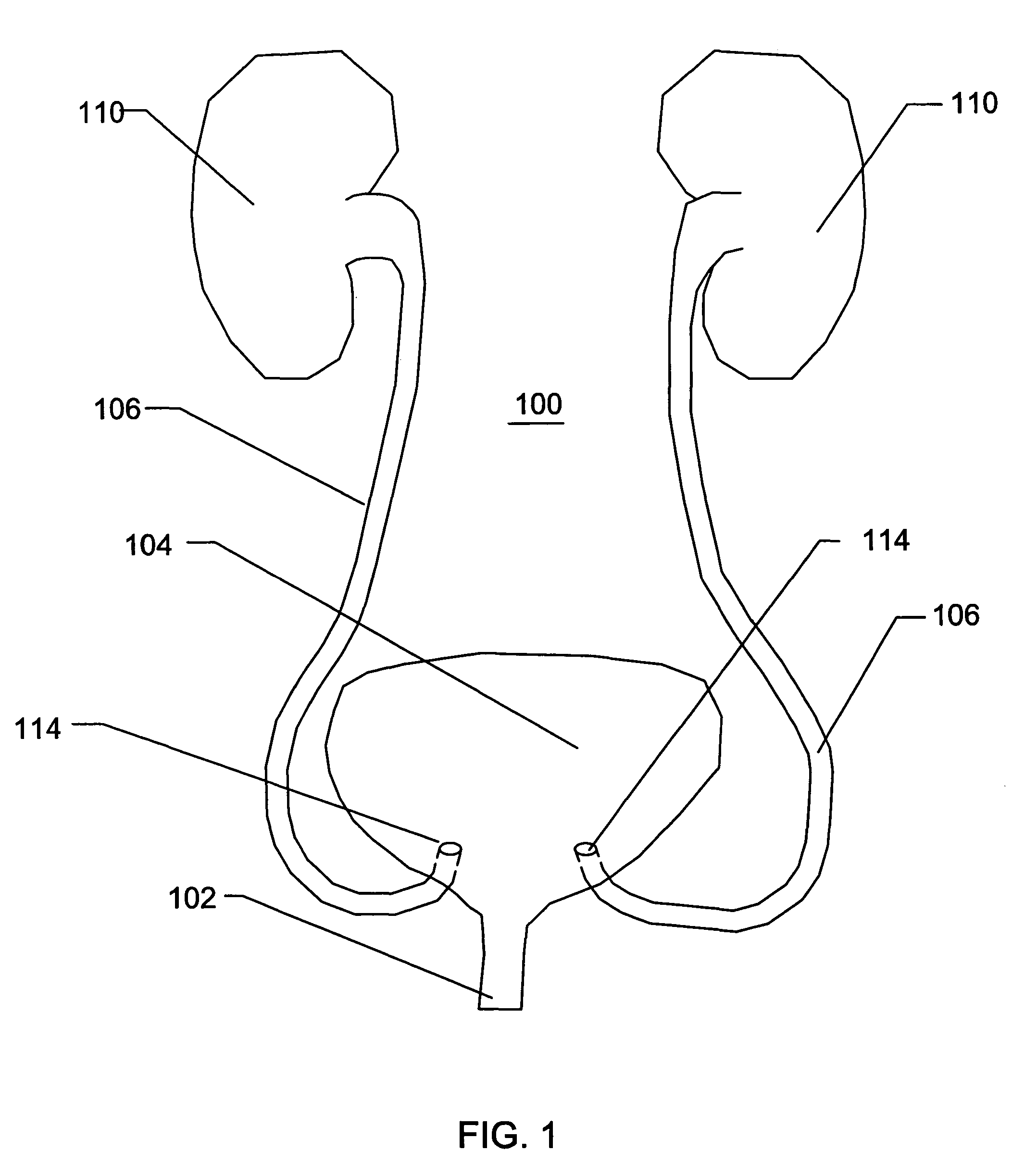
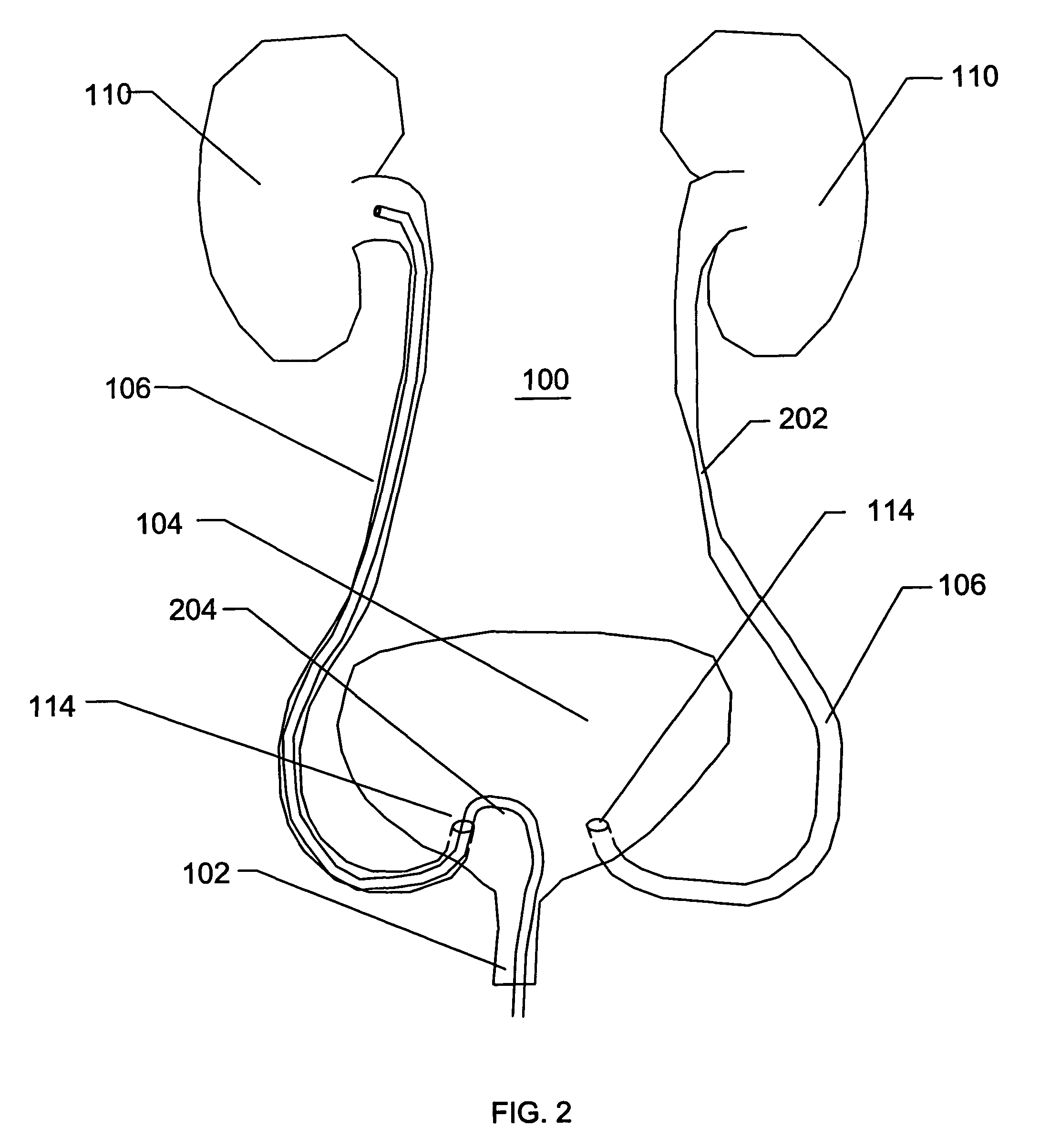
[0052]With reference to the FIGS. 1-14, various embodiments of a catheter or a sheath will be described. A catheter or a sheath, can be described as being an axially elongate hollow substantially tubular structure having a proximal end and a distal end. The axially elongate structure further has a longitudinal axis and preferably has an internal through lumen that can extend from the proximal end to the distal end for the passage of instruments, implants, fluids, tissue, or other materials. The axially elongate hollow tubular structure is preferably generally flexible and capable of bending, to a greater or lesser degree, through one or more arcs in one or more directions perpendicular to the main longitudinal axis. In many embodiments, the tubular structure and the internal lumen have a substantially circular cross-section but in other embodiments the cross-section can have another shape (e.g., oval, rectangular etc.)

[0053]As is commonly used in the art of medical devices, the prox...


PUM


Abstract

Disclosed is an expandable transluminal sheath, for introduction into the body while in a first, low cross-sectional area configuration, and subsequent expansion of at least a part of the distal end of the sheath to a second, enlarged cross-sectional configuration. The distal end of the sheath is maintained in the first, low cross-sectional configuration and expanded using a radial dilatation device. In an exemplary application, the sheath is utilized to provide access for a diagnostic or therapeutic procedure such as ureteroscopy or stone removal.

Description

PRIORITY CLAIM[0001]This application claims priority to under claims priority under 35 U.S.C. 119(e) of Provisional Application 60 / 660,512, filed Mar. 9, 2005 and Provisional Application 60 / 608,355, filed on Sep. 9, 2004, the entirety of which are hereby expressly incorporated herein by reference.BACKGROUND OF THE INVENTION[0002]1. Field of the Invention[0003]The invention relates to medical devices for transluminally accessing body lumens and cavities and, more particularly, to methods and devices for accessing the mammalian urinary tract.[0004]2. Description of the Related Art[0005]A wide variety of diagnostic or therapeutic procedures involves the introduction of a device through a natural access pathway such as a body lumen or cavity. A general objective of access systems, which have been developed for this purpose, is to minimize the cross-sectional area of the access lumen, while maximizing the available space for the diagnostic or therapeutic instrumentation. These procedures...

Claims


Application Information

Patent Timeline
Patent Type & Authority Patents(United States)
IPC IPC(8): A61M31/00A61F2/958A61M25/10
CPCA61B17/3439A61M25/0017A61B17/0218A61M27/008A61B17/22A61B17/22031A61M25/0662A61M2025/0024A61M2025/0681A61M2025/1081A61B2017/0225
Inventor LENKER, JAYNANCE, EDWARD J.BISHOP, JOSEPHKICK, GEORGE F.
Owner ONSET MEDICAL CORP
Why Eureka
Try Eureka