Auto-sensing, automatic adjusting exhaust baffle

a technology of automatic adjustment and exhaust baffle, which is applied in the direction of combustion engines, machines/engines, mechanical equipment, etc., can solve the problems of increasing the noise level of the open exhaust pipe, excessive backpressure, and generally exceeding the acceptable audible limits, and achieves the effect of enhancing the throttle respons

Inactive Publication Date: 2011-03-01
DE LEO THEODORE +1
View PDF12 Cites 4 Cited by
  • Summary
  • Abstract
  • Description
  • Claims
  • Application Information

AI Technical Summary

Benefits of technology

An objective of the invention is to overcome at least some of the drawbacks relating to the compromise designs of aftermarket exhaust pipes that have had the stock baffles removed. The invention generally relates to a responsive exhaust baffle, generally for motorcycle exhaust pipes, and is especially applicable to aftermarket motorcycle exhaust pipes with a straight-through pipe design. The current embodiment of the invention, when used allows for carefree automatic tuning of the motorcycle exhaust, thru out the power band, referred to herein as auto-sensing, automatic adjusting exhaust baffle. While obtaining the desired sound and power, the user will have the additional benefit of an enhanced throttle response.
An object is to provide a auto-sensing, automatic adjusting exhaust baffle, for reducing noise level emissions produced by internal combustion engines, while improving overall engine performance, i.e., torque and horsepower and improved engine performance throughout the power band. According to the invention, a flow passage is formed between an inlet and an outlet, which opens into a region at ambient pressure. The auto-sensing, automatic adjusting exhaust baffle uses a main cylindrical disk body that acts not only as an spent exhaust gas conduit, it acts as a mechanical support for the shaft and sphere assembly, said sphere assembly houses a pressed internal bearing, sliding linearly on a shaft, and said sphere and bearing being acted upon by a compression spring mounted axially over the diameter of the shaft. The auto-sensing, automatic adjusting exhaust baffle uses a spring loaded spherical shape to evacuate spent exhaust gas, thus scavenging the surrounding exhaust gases to adjust the backpressure, while quieting the resonance of noise exiting the exhaust pipe at lower rpm's. It may also be contained in a static position by fixing it in place with a fastening device, rather than sliding along linearly. This optional positioning will provide for a quieter operation thru out the power band.

Problems solved by technology

Such an arrangement, which typically is referred to as open drag pipe, is typically a configuration that will not only reduce performance in the low to mid range of the RPM band, it will typically increase the noise level being emitting from the open exhaust pipe, which is generally beyond the acceptable audible limits.
On the other hand the correct amount of backpressure is required for a combustion engine to work efficiently through out all operating conditions, but too much backpressure is the result of a restrictive exhaust system.
Since the gases cannot escape at the proper velocity, your engine has to work harder without yielding greater power.
In general, you lose horsepower, torque and fuel economy.

Method used


Image

  • Auto-sensing, automatic adjusting exhaust baffle
  • Auto-sensing, automatic adjusting exhaust baffle
  • Auto-sensing, automatic adjusting exhaust baffle

Examples


Embodiment Construction

The present inventions now will be described more fully hereinafter with reference to the accompanying drawings, in which some, but not all embodiments of the invention are shown. Indeed, these inventions may be embodied in many different forms and should not be construed as limited to the embodiments set forth herein; rather, these embodiments are provided so that this disclosure will satisfy applicable legal requirements. Like numbers refer to like elements throughout.

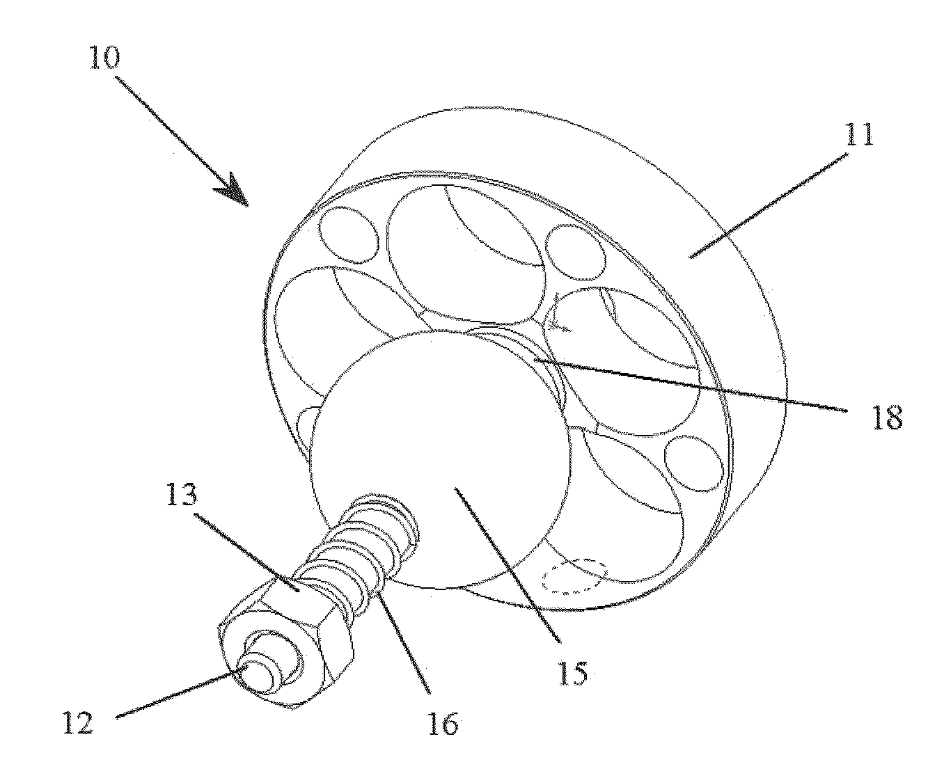
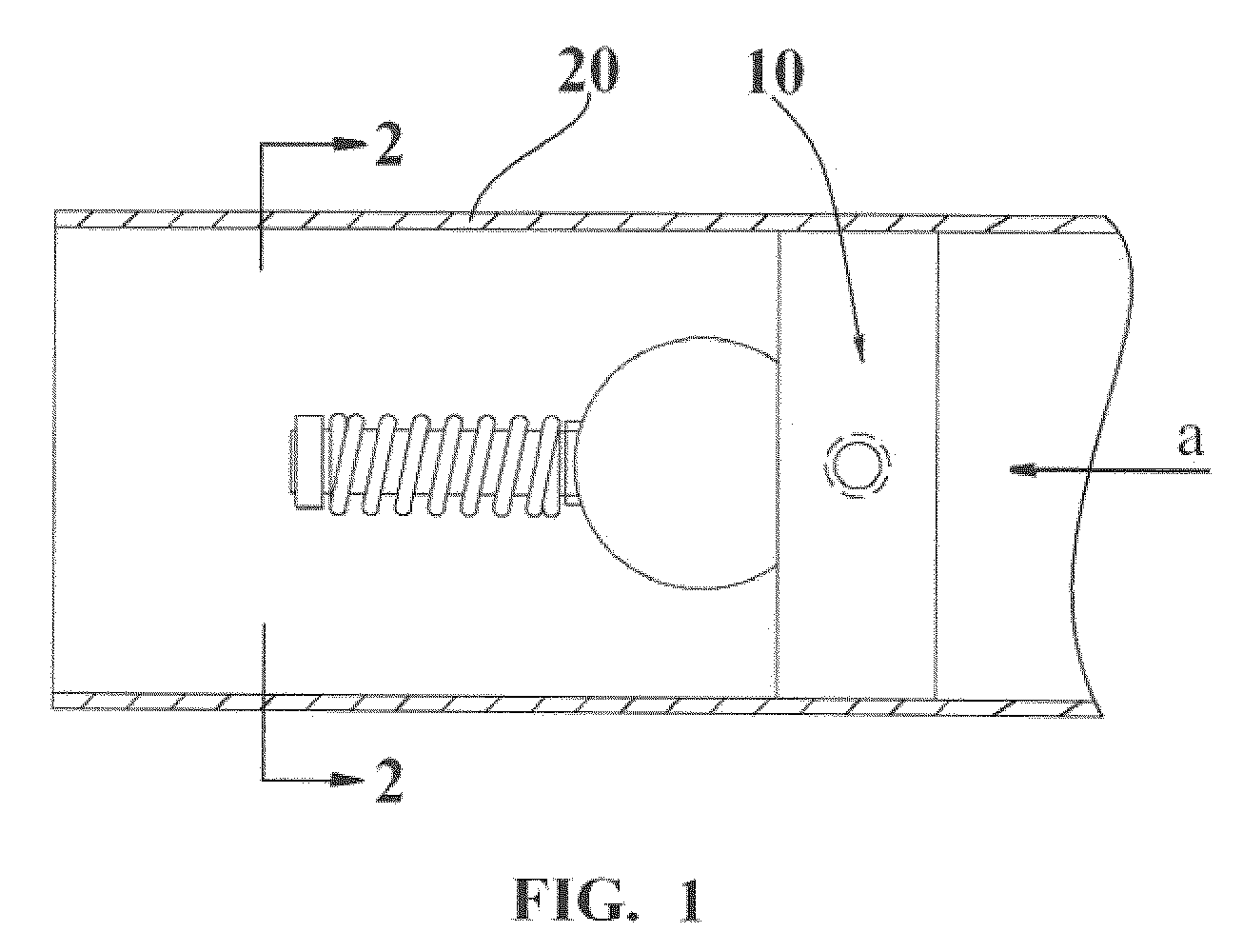
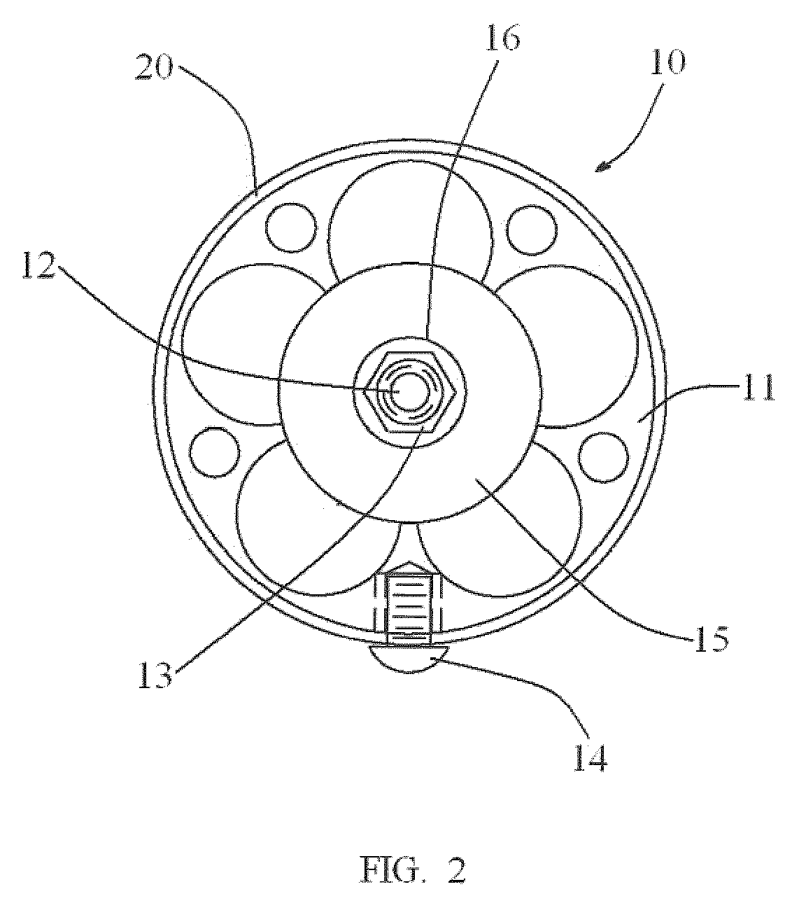
Turning now descriptively to the drawings referring to FIGS. 1 and 2, in which similar reference characters denote similar elements throughout the several views, the figures illustrate a main cylindrical disk body 11 that contains a spring 16, linear glide sphere 15 that moves along a shaft 12 according to the exhaust gas backpressure and varying flow rates. Exhaust gasses flow in a direction indicated by an arrow a, into said main cylindrical disk body 11 via the exhaust pipe 20, connected to an combustion engine (n...


PUM


Abstract

An auto-sensing, automatic adjusting exhaust baffle; for reducing noise emissions produced by internal combustion engines, while improving overall engine performance, i.e., torque and horsepower. The design uses a spherical shape to evacuate spent exhaust gas, thus scavenging the surrounding exhaust gases to adjust the backpressure, while reducing the noise exiting the exhaust pipe at lower rpm's. The device uses a sphere with an internal bearing; sliding linearly on a shaft and said sphere and bearing being acted upon by exhaust gasses and a compression spring mounted axially over the diameter of the shaft. The purpose of this device is to reduce noise while improving tuning of the air / fuel intake system, by adjusting backpressure of the exhaust system. The lesser amount of exhaust pressure, the less the sphere moves, as in idle to just off of idle, this results in a quiet operational mode of the invention. As more exhaust pressure is presented, as in higher throttle positions, the more the sphere moves away from the discharge ports, the louder the sound will be from the exit end of the exhaust pipe, this results in the active mode of the invention, obtaining the desired sound and adjusted backpressure throughout the power band.

Description

STATEMENT REGARDING FEDERALLY SPONSORED RESEARCH OR DEVELOPMENTNot ApplicableREFERENCE TO SEQUENCE LISTING, A TABLE, OR A COMPUTER PROGRAM LISTING COMPACT DISK APPENDIXNot ApplicableFIELD OF THE INVENTIONThe present invention relates generally to and more specifically it relates to exhaust baffles, and in particular to such baffles which are responsive to the exhaust characteristics of a combustion engine.BACKGROUND OF THE INVENTIONThe present day motorcycle enthusiast on many occasions, remove the stock baffles that are located within the exhaust pipe. The objective of such action is an attempt to improve the sound that is emitted from the exhaust pipe. The sound emitted is a pressure wave that builds from alternating low and high air pressure that moves at the speed of sound. Such an arrangement, which typically is referred to as open drag pipe, is typically a configuration that will not only reduce performance in the low to mid range of the RPM band, it will typically increase th...

Claims


Application Information

Patent Timeline
Patent Type & Authority Patents(United States)
IPC IPC(8): F01N1/16
CPCF01N1/083
Inventor DE LEO, THEODORECOATE, RICHARD S.
Owner DE LEO THEODORE
Why Eureka
Try Eureka