
EUV plasma discharge lamp with conveyor belt electrodes

a conveyor belt electrode and discharge lamp technology, applied in the field of plasma discharge lamps, can solve the problems of shortening the reducing the service life of the lamp, so as to achieve the effect of high input power and more compact design

Active Publication Date: 2011-03-01
USHIO DENKI KK
View PDF9 Cites 6 Cited by
  • Summary
  • Abstract
  • Description
  • Claims
  • Application Information

AI Technical Summary

Benefits of technology

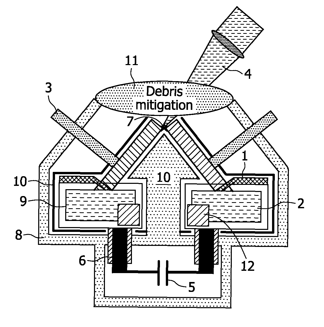
[0006]It is an object of the present invention to provide a plasma discharge lamp for generating EUV radiation and / or soft X-rays by means of an electrically operated discharge, which can use metal vapor for plasma generation and allows a more compact design for high input powers.
[0009]With such conveyer belts as electrodes, i.e. as cathode and anode, of the plasma discharge lamp it is possible to achieve a compact lamp design and at the same time a sufficient cooling of the electrodes for a higher input power.
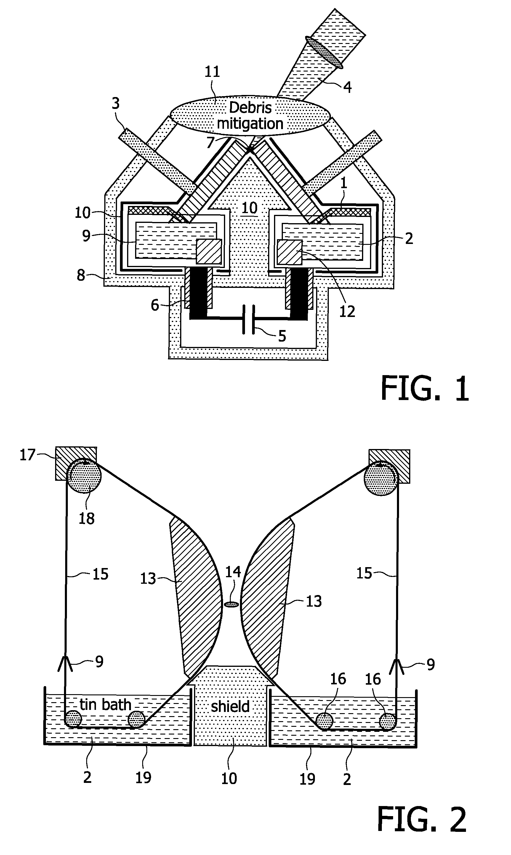
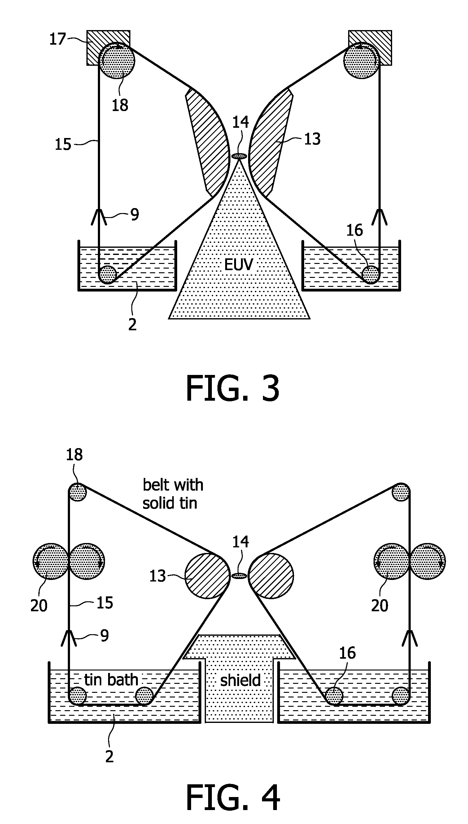
[0010]The proposed plasma discharge lamp is preferably designed like the plasma discharge lamp of WO 2005 / 025280 A2, which is incorporated herein by reference, except of the design and movement of the two electrodes. The use of conveyer belts instead of electrode wheels has the further advantage that it allows more flexibility in the mechanical design. For instance, the contact surface between the belt and the melted metal can be easily increased by making several passes or turns under the surface of the melted metal in the corresponding metal bath. This improves the cooling of the belt significantly.
[0011]In one embodiment of the proposed plasma discharge lamp the shaper elements are formed to provide a curved surface at the gap, wherein the curved surface has a sufficiently large smallest radius of curvature to allow a high driving speed of the belt without the risk that liquid metal tears off at the shaper elements due to centrifugal forces. Since the remaining portion of the shaper elements is not in contact with the conveyer belts, this portion can be formed to occupy a minimum space. Such shaper elements may have the profile of a segment of a circle, for example made of a cut off portion a circular disk with a thickness of the width of the belt or smaller. Also other curved forms are possible. Compared with rotating wheels, therefore, such shaper elements can provide a large radius of curvature of the electrodes at the gap without occupying the same space. Further required deflection elements for the guidance of the belt with a far smaller curvature are then positioned in the baths of the liquid metal or are combined with an appropriate cover which prevents the tearing off of the liquid metal film due to centrifugal forces.
[0012]The electrical connection between the capacitor bank of the power supply and the electrodes can be achieved through the baths of the liquid metal in the same manner as already disclosed in WO 2005 / 025280 A2. Nevertheless, since the shaper elements in the above embodiment are fixed and do not rotate, the electrical connection to the electrodes can also be achieved through the shaper elements. This has the advantage that the containers with the metal melt can be separated by a sufficient distance from one another to allow the emission of plasma generated EUV radiation and / or soft X-rays in this direction, i.e. the radiation can pass between the two containers. Electrical connection of the electrodes through the containers in such a case may result in an undesirably high inductance of the system.
[0014]In a further embodiment of the present plasma discharge lamp, the shaper elements are formed of rotating rollers with a smaller radius of curvature as that of the above embodiment. In order to avoid the tearing off of liquid metal from the surface at these shaper elements, additional pairs of cooled rollers are provided upwards the shaper elements with respect to the driving direction of the belts. These additional rollers are cooled such that the liquid metal film on the surface of the belt, which passes between the pair of cooled rollers is cooled down below the melting temperature, thereby forming a solid layer on the conveyer belt. With this solid layer, the metal melt does not move and the problem of the centrifugal forces at higher driving speeds does not occur so that the curvature of the shaper elements and other deflection elements downwards of the cooled rollers can be held small even at higher driving speeds.

Problems solved by technology

Hence, a very long life time of the lamp is obtained.
However, the rotation frequency is limited for the following reason.
The drawback of this solution is that extremely large wheels are necessary which improves neither the mechanical stability nor the compactness of the lamp.

Method used


Image

  • EUV plasma discharge lamp with conveyor belt electrodes
  • EUV plasma discharge lamp with conveyor belt electrodes
  • EUV plasma discharge lamp with conveyor belt electrodes

Examples


Embodiment Construction

[0023]The EUV plasma discharge lamp of FIG. 1 has already been described in the introductory portion of the present description. In the following examples several embodiments of the design of the electrodes of the proposed EUV plasma discharge lamp are described, which can be used to substitute the electrode arrangement of the EUV plasma discharge lamp of FIG. 1. The further components of this lamp can be identical to this known lamp so that these components are not further explained in connection with the following examples.

[0024]In order to achieve a high rotational speed of the electrode wheels of FIG. 1, which is necessary for a better cooling and corresponding higher input power, the radius of the electrode wheels has to be increased in order to avoid the tearing off of the liquid metal film by centrifugal forces. With such large wheels, however, a compact EUV lamp can not be realized. Large wheels are avoided in the present EUV lamp, when conveyer belts as electrodes in combin...


PUM


Abstract

The present invention relates to a plasma discharge lamp for generating EUV radiation and / or soft X-rays by means of an electrically operated discharge. The proposed lamp comprises at least two electrodes arranged in a discharge space at a distance from one another to form a gap which allows the ignition of a plasma (14) in a gaseous medium between said electrodes. A metal applying device applies a metal to a surface of said electrodes. The electrodes are formed of conveyer belts (15) driven to transport the metal to said gap, wherein for each of the electrodes a shaper element (13) is provided at the gap to ensure a proper form and distance of the electrodes at the gap. An energy beam device (4) is adapted to direct an energy beam onto at least one of said surfaces in the gap evaporating said applied metal at least partially thereby producing said gaseous medium. With the proposed plasma discharge lamp high input powers can be achieved at a compact design of the lamp.

Description

FIELD OF THE INVENTION[0001]The present invention relates to a plasma discharge lamp for generating EUV radiation and / or soft X-rays by means of an electrically operated discharge, comprising at least two electrodes arranged in a discharge space at a distance from one another to form a gap which allows the ignition of a plasma in a gaseous medium between said electrodes, a device for applying a metal to a surface of said electrodes in said discharge space and an energy beam device adapted to direct an energy beam onto at least one of said surfaces in the gap evaporating said applied metal at least partially thereby producing said gaseous medium.[0002]Plasma discharge lamps for generating EUV radiation (EUV: extreme ultraviolet) or soft X-rays, i.e. radiation in the wavelength region of around 1 nm to 20 nm, are required in the field of EUV lithography, microscopy or metrology. For most applications high conversion efficiency together with a long life time of the lamps is desirable.B...

Claims


Application Information

Patent Timeline
Patent Type & Authority Patents(United States)
IPC IPC(8): H05G2/00
CPCH05G2/005H05G2/003H05G2/00H01J61/62
Inventor JONKERS, JEROENNEFF, JAKOB WILLIPRUEMMER, RALF
Owner USHIO DENKI KK
Learn More