Method and apparatus for detecting misfires and idenfifying causes

Active Publication Date: 2011-03-01
AUTOMOTIVE TEST SOLUTIONS
View PDF4 Cites 45 Cited by
  • Summary
  • Abstract
  • Description
  • Claims
  • Application Information

AI Technical Summary

Benefits of technology

[0013]It is an object of the present inventions to provide a misfire detector which is easy to use, reasonably pric

Problems solved by technology

Since the conception of the internal combustion engine, combustion efficiency has been a problem.
Early on it was a source of power loss.
A drawback with the FTP requirement is that an intermittent misfire will not produce emission levels exceeding 1.5% of the FTP tailpipe emissions.
Such misfire(s) will, however, cause a drivability problem with the vehicle.
It is also known that some vehicles have powertrain control module programming errors that detect and report the incorrect cylinder for the misfire condition.
Such inefficiencies range from a complete misfire (e.g., where the fuel-air mixture does not ignite at all) to conditions where the efficiency is less than achieved in a normally running engine.
Examples of the latter include: lean air/fuel ratio; rich air/fuel ratio; ignition spark weak or out of time; low compression within the cylinder;

Method used


Image

  • Method and apparatus for detecting misfires and idenfifying causes
  • Method and apparatus for detecting misfires and idenfifying causes
  • Method and apparatus for detecting misfires and idenfifying causes

Examples


Embodiment Construction

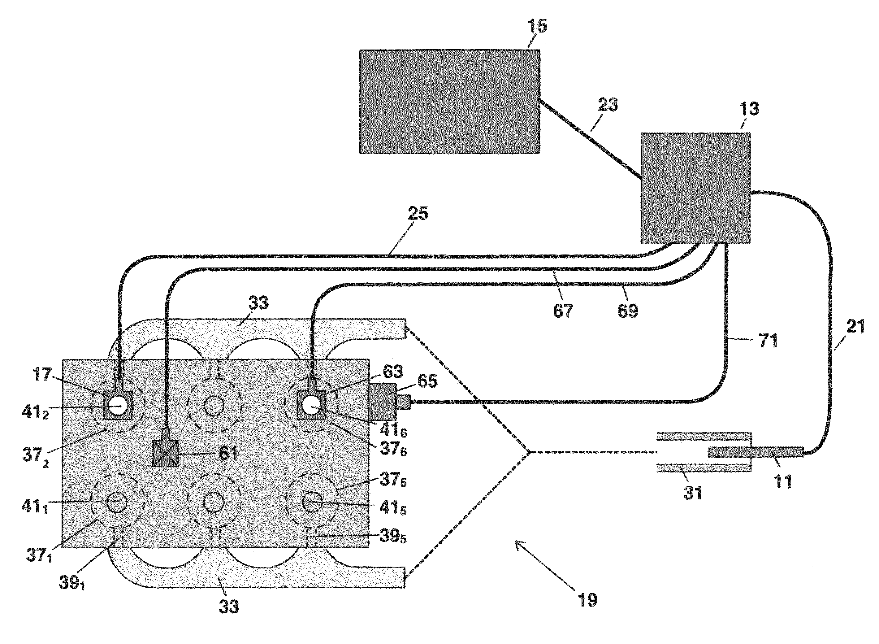
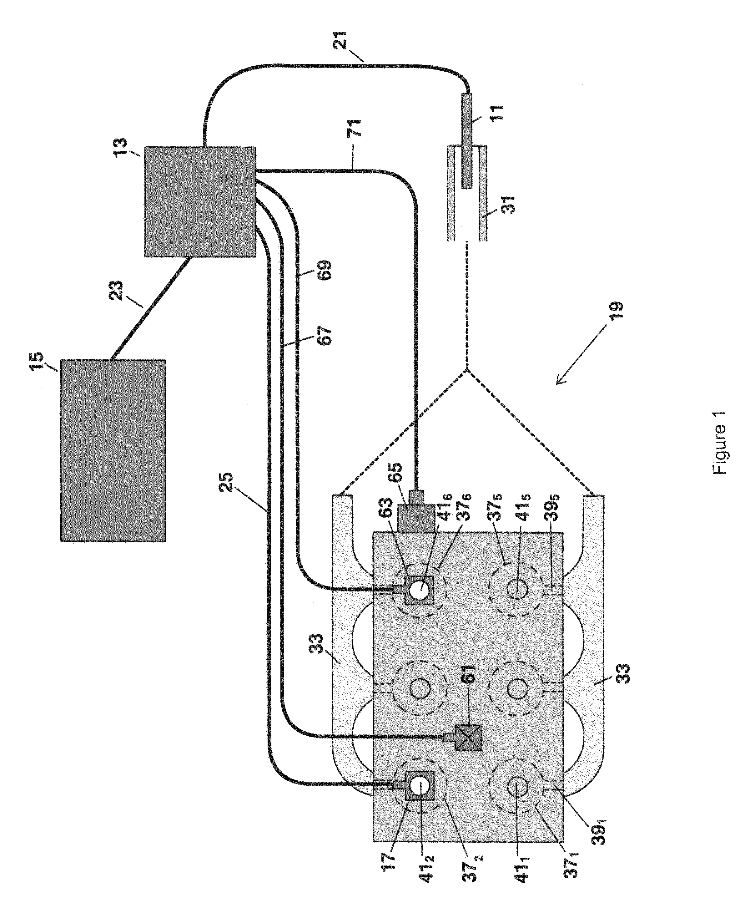
[0086]With reference to FIG. 1, the misfire detector system of the present invention includes exhaust pressure sensing device 11, A / D converter 13, computer 15 and apparatus 17 for capturing a trigger signal from engine 19. Exhaust pressure sensor 11 is connected to a conventional A / D converter 13 by cable 21 which, in turn, is connected to computer 15 by cable 23. Trigger apparatus 17 is connected to A / D converter 13 by cable 25.

[0087]Exhaust pressure sensor 11 may be a FirstLook sensor manufactured by SenX Technology, LLC (“SenX”) or a MLH Series pressure sensor from Honeywell, or an All Sensor's H20 Hall Effect sensor, or equivalent. These devices will be referred to as a“basic pressure transducer”. As explained later, improved performance is obtained with the use of the venturi amplified sensor disclosed and claimed in co-pending U.S. patent application Ser. No. 11 / 879,565, the disclosure of which is incorporated by reference. With the venturi sensor multiple misfires, including...


PUM


Abstract

A method of identifying misfires in an engine including: running the engine; measuring the pressure pulses from the exhaust; generating a waveform from the measured pulses; dividing the waveform into segments; associating each waveform segment with the cylinder which generated the pulse; and examining each segment for features which indicate a misfire. Also disclosed is methodology for checking the performance of an engine including cam timing and identifying the probable cause(s) of misfires. This includes generating a cylinder pressure waveform from the measured pressure changes in a cylinder and analyzing the magnitude and timing of at least one of the pressure changes in such cylinder. Further disclosed is methodology for analyzing the pressure changes in the engine's intake manifold and in the crankcase. Finally, additional diagnostic procedures are disclosed for: checking the ignition timing of an engine; and using the apparatus and methods with additional instrumentation including gas analyzers.

Description

CLAIM OF PRIORITY[0001]This application is a continuation-in-part of and claims the priority of application Ser. No. 11 / 899,271, filed Sep. 4, 2007 which, in turn, is a continuation-in-part and claims the priority of provisional application Ser. No. 60 / 842,310, filed Sep. 5, 2006. This application is also a continuation-in-part and claims the priority of application Ser. No. 11 / 811,634 filed Jun. 8, 2007 which, in turn, is a continuation-in-part and claims the priority of provisional application Ser. No. 60 / 812,525 filed Jun. 8, 2006.FIELD OF THE INVENTIONS[0002]These inventions relate to automotive test equipment. More particularly, the present inventions relate to apparatus and methods of detecting cylinder misfires, including both intermittent and multiple misfires and then identifying the probable cause(s) of such intermittent or multiple misfires.BACKGROUND OF THE INVENTIONS[0003]The 4 cycle internal combustion engine has four cycles or four strokes that occur in 720° of cranks...

Claims


Application Information

Patent Timeline
IPC IPC(8): G01M15/00F02P5/14
CPCG01M15/11
Inventor PEDERSON, NEAL R.THOMPSON, BERNIE C.
Owner AUTOMOTIVE TEST SOLUTIONS
Why Eureka
Try Eureka