
Method and system for data synchronization

a data synchronization and data technology, applied in the field of data synchronization technology, can solve the problems of inability to real-time synchronize, large data flow, and complex telecommunication network, and achieve the effects of reducing the volume of data to be synchronized, ensuring network smoothness and network stability, and reducing network load

Active Publication Date: 2011-03-01
HUAWEI TECH CO LTD
View PDF14 Cites 17 Cited by
  • Summary
  • Abstract
  • Description
  • Claims
  • Application Information

AI Technical Summary

Benefits of technology

[0015]The embodiments of the invention provide a method and a system for data synchronization, thereby lowering the volume of data to be synchronized and improving the data synchronization efficiency.
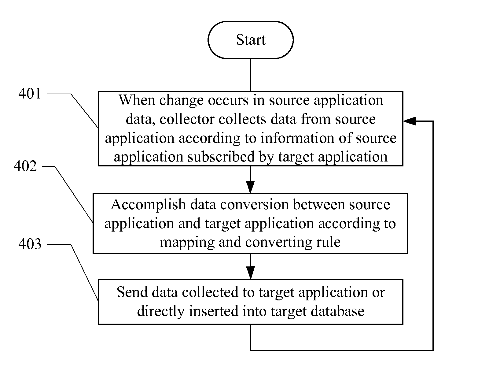
[0022]It can be seen from the method according to the above embodiment of the invention that, in the embodiment of the invention, when a change occurs in the source application data, data is collected from a source application according to the source application information subscribed by a target application, so that a subscription relationship of the target application on the source application and the type of data to be collected will be specified, and the range of data collection will be reduced to a single source application, and even to a specific data object of the source application. Moreover, when a change occurs in the source application data, an operation of data synchronization will be triggered, so that “On-Demand Synchronization” may be realized. At the same time, because only data needed is collected, not all the data changes of the source application will cause a collection and synchronization process. Accordingly, volume of data to be synchronized may be lowered greatly, network load may be alleviated, and network smoothness and network stability may be guaranteed.
[0023]It can be seen from the system according to the above embodiment of the invention that, in the embodiment of the invention, because a data collection unit and a distribution unit are designed for data synchronization, when a change occurs in the source application data, the data collection unit will collect data from a source application according to the source application information subscribed by a target application, and the distribution unit sends the data collected to the target application or directly inserts the data collected into a target database, so that “On-Demand Synchronization” may be realized. At the same time, because only data needed is collected, not all the data changes of the source application will cause a collection and synchronization process, and thus volume of data to be synchronized may be lowered greatly, and data synchronization efficiency may be improved.

Problems solved by technology

For example, in telecommunication network management systems, a telecommunication network becomes more and more complex.
This method has the following disadvantages: 1) real-time synchronization cannot be realized, and configuration modification on a network element is usually reflected to the network management system in a period of time; and 2) a query process will be carried out no matter whether configuration modification appears, and all the configuration data may be checked; thus, the data flow may be very large.
But, in respect that the data volume modified each time is usually small, the method in which all the data are processed each time a small part of data are modified will apparently have a low efficiency.
In comparison with the first method, the realization of this method is relatively complex; moreover, redundant data that are not necessary to be processed may usually be included.
1) The volume of data to be synchronized is too large. Timed synchronization is to synchronize all the data; for synchronization using relational database, although the above method for obtaining a minimal data variation set may be employed, the basis for determining whether to synchronize is till the variation of data. However, practically not all the changed data needs to be synchronized. Therefore, it cannot be ensured that the volume of data to be synchronized is minimized.
2) Real-time arrival of data cannot be guaranteed. Apparently, it is difficult to realize real-time synchronization of data in timed synchronization. If real-time synchronization is needed, synchronization operation must be performed all the time, such a large data transmission volume is difficult to be realized and it is uneconomical. For the method for data synchronization using relational database, no technical measure for ensuring real-time data synchronization is given in the above prior art.
3) Transaction integrity cannot be guaranteed. No matter it is timed synchronization or synchronization using relational database, the obtaining of data is ruleless and orderless. For example, during the synchronization process of data generated by operating an event, if the event comprises a plurality of steps arranged in time sequence and each step is the triggering condition of the subsequent step, when the information of these steps is synchronized to the target application, the information data of these steps obtained by the target application should be consistent with the order of information data of the steps for synchronizing the data source; otherwise, the order of information of these steps synchronized to the target application may be disturbed, thus the steps may not be executed again.
4) Data filtration and data screening cannot be realized. In the above prior art, data to be synchronized are nonselective. All the data will be synchronized, or the data will be synchronized when it is changed. Therefore, the data that should be synchronized may not be synchronized, while the data that should not be synchronized may be synchronized. As a result, the efficiency will be very low and the data transmission volume will be very large.
5) Other systems interested in changed data cannot be notified in real time. In the above prior art, data can only be synchronized to a fixed target application. Thus, once the target application is changed, it will be difficult to meet the requirement of data synchronization.

Method used


Image

  • Method and system for data synchronization
  • Method and system for data synchronization
  • Method and system for data synchronization

Examples


Embodiment Construction

[0034]The invention will now be described in detail in conjunction with the embodiments and drawings of the invention.

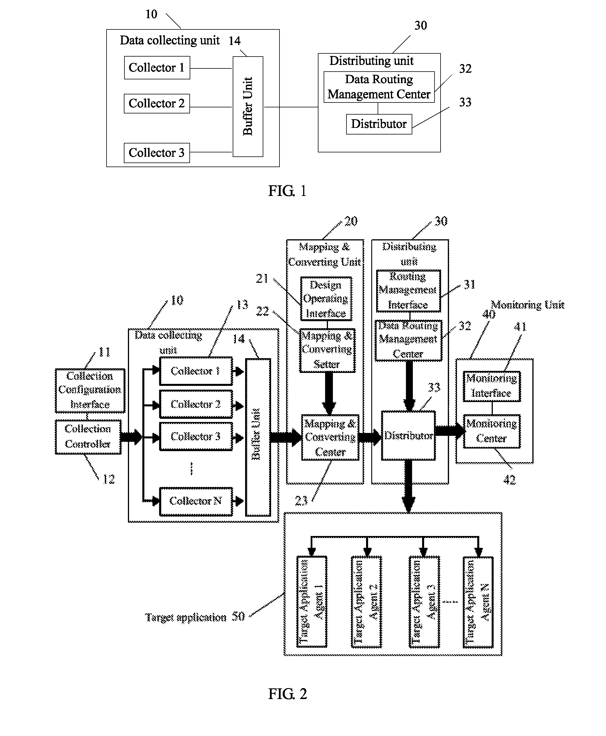
[0035]Referring to FIG. 1, it is a functional block diagram of a system for data synchronization, according to one embodiment of the invention.

[0036]In this embodiment, the system for data synchronization includes a data collection unit 10 and a distribution unit 30. The data collection unit 10 may include one or more collectors, for collecting data from the source application, according to the source application information subscribed by a target application when change occurs in the source application data; and in FIG. 1, there are three collectors shown. Each collector may be set to trigger a collection event when change occurs in the source application data.

[0037]The data collection unit 10 may include a buffer unit 14. The collector may write the data collected to the buffer unit 14 in the unit of transaction; in other words, a transaction ID and operation seque...


PUM


Abstract

A data synchronization system and method. The method includes that when a change happens in a source application, data is collected from a source application based on a target application subscribing the source application and collection data is transmitted to the target application or is directly inserted to target database. The system includes data collection unit and distribution unit. The present invention may realize synchronization on demand, simultaneously reduce greatly synchronous data quantity, decrease network load, and guarantee smoothness and stabilization of network. The present invention applies to data synchronization of enterprise internal / external data systems, telecommunication networks, etc.

Description

CROSS-REFERENCE TO RELATED APPLICATIONS[0001]This application is a continuation of International Patent Application No. PCT / CN2007 / 000995, filed Mar. 28, 2007, which claims priority to Chinese Patent Application No. 200610072096.8, entitled “System for Data Synchronization and Method Thereof,” filed Apr. 10, 2006, both of which are hereby incorporated by reference in their entirety.FIELD OF THE INVENTION[0002]The present invention relates to data synchronization technology, and in particular, to a method and a system for data synchronization based on subscription relationship.BACKGROUND OF THE INVENTION[0003]In the information age, large volumes of information needs to be collected, transmitted and managed; thus, strict requirements are laid on the existing information application technology. Therefore, information synchronization and information sharing are of special importance.[0004]Data synchronization technology has been widely applied to various industries such as communicatio...

Claims


Application Information

Patent Timeline
Patent Type & Authority Patents(United States)
IPC IPC(8): G06F15/16
CPCG06F17/30581H04L12/24H04L41/00H04L67/1095H04L69/08G06F16/275
Inventor ZHU, ZHONGCHUWANG, YONGFENGZHOU, FEISHI, MINGZHUHE, WEIWANG, YUNLONG
Owner HUAWEI TECH CO LTD
Learn More