Relay connector unit and electronic device control system

a technology of electronic devices and connectors, applied in the direction of coupling device connections, pulse techniques, instruments, etc., can solve the problems of disadvantageous cost, difficult to standardize the connectors with built-in electronic components, and complicated structure of female types, so as to facilitate system structure, simplify the connection structure, and reduce the cost

Active Publication Date: 2011-03-01
YAZAKI CORP
View PDF10 Cites 10 Cited by
  • Summary
  • Abstract
  • Description
  • Claims
  • Application Information

AI Technical Summary

Benefits of technology

As descried above, the relay connector unit according to this invention includes a first connecting unit to which a first wire harness connected to the electronic control unit is connected; a second connecting unit to which second wire harnesses connected to the plural electronic devices, respectively are connected; and a transferring unit which transfers the information received by each of these connecting unit to the pertinent unit / device. For this reason, even when the electronic control unit collectively controls the plural electronic devices, only the first wire harness may be connected to the electronic control unit, thereby simplifying the connecting structure such as the number of circuits in the electronic control unit. Further, the relay connector unit, which is located among the wire harnesses remote from the electronic devices, is advantageous from the viewpoint of strength as compared with a conventional relay connector unit connected to the electronic devices. This prevents the electronic control unit from being upsized, permits the plural electronic devices to be controlled, and contributes the cost reduction. Further, since the relay connector unit according to this invention can easily deal with an increase in the number of the electronic devices to be controlled by the electronic control unit, the system structuring can be facilitated. Further, even where the connecting structure of the electronic device has a peculiar shape, it has only to be connected to the second connecting unit by the second wire harness, thereby permitting the relay connector units to be standardized.
Further, since the relay connector unit transmits the second information from the electric device, after supplemented with the address data, to the electronic control unit, multiplex communication between the plural relay connector units and the electronic control unit can be realized through the first wire harness. Thus, even if the number of the relay connector units is increased, the common first wire harness has only to be connected to the electronic control unit. Thus, upsizing of the electronic control unit is prevented and a larger number of electronic devices can be collectively controlled.
As described above, in the relay connector unit and electronic device control system according to this invention, the first wire harness is connected to the first connecting unit of the relay connector unit, the plural second wire harnesses are connected to the second connecting unit of the relay connector unit, the electronic control unit is connected to the first wire harness and the plural electronic devices are connected to the second wire harnesses, respectively. For this reason, only the first wire harness may be connected to the electronic control unit so that the connecting structure such as the number of circuits in the electronic control unit can be simplified. Further, since the plural second wire harnesses can be collectively connected to the relay connector unit, the plural electronic devices can be easily established at different places, thereby greatly facilitating the system structuring. Further, if the relay connector unit is prepared in the form of the wire harness assembly, the electronic control unit and the electronic devices have only to be connected to the wire harnesses of the wire harness assembly so that the production efficiency can be improved.

Problems solved by technology

So, it is difficult to standardize the connectors with a built-in electronic component.
The female type is very complicate in structure, and so disadvantageous in cost.
This results in an increase in cost.

Method used


Image

  • Relay connector unit and electronic device control system
  • Relay connector unit and electronic device control system
  • Relay connector unit and electronic device control system

Examples


Embodiment Construction

Now referring to FIGS. 2 to 4, an explanation will be given of a detailed description of a relay connector unit, a wire harness assembly and an electronic device control system according to this invention.

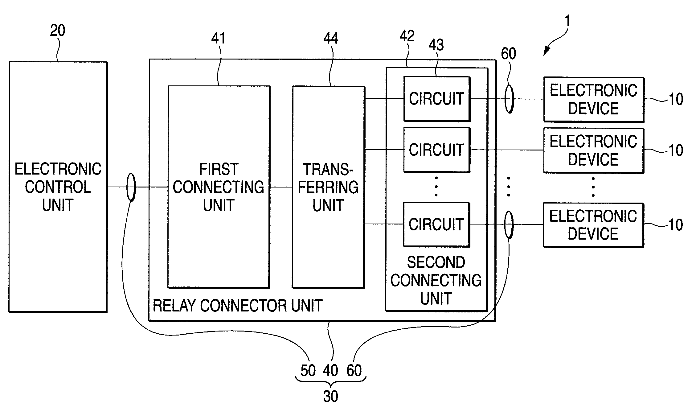
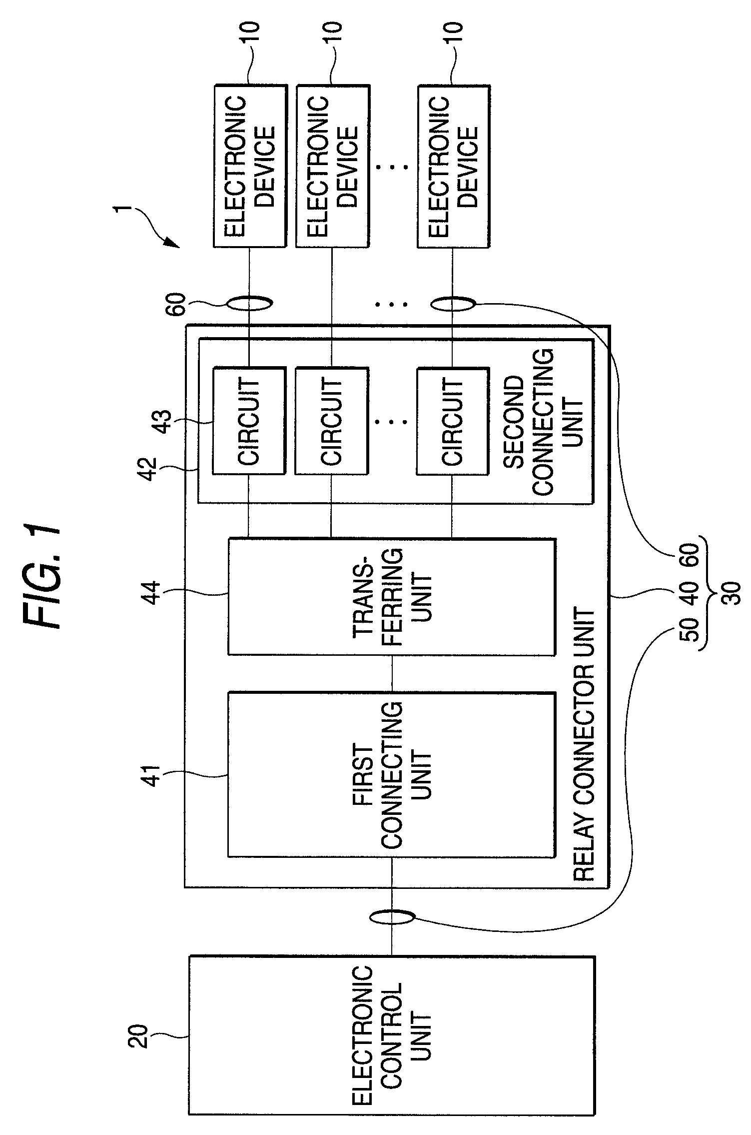
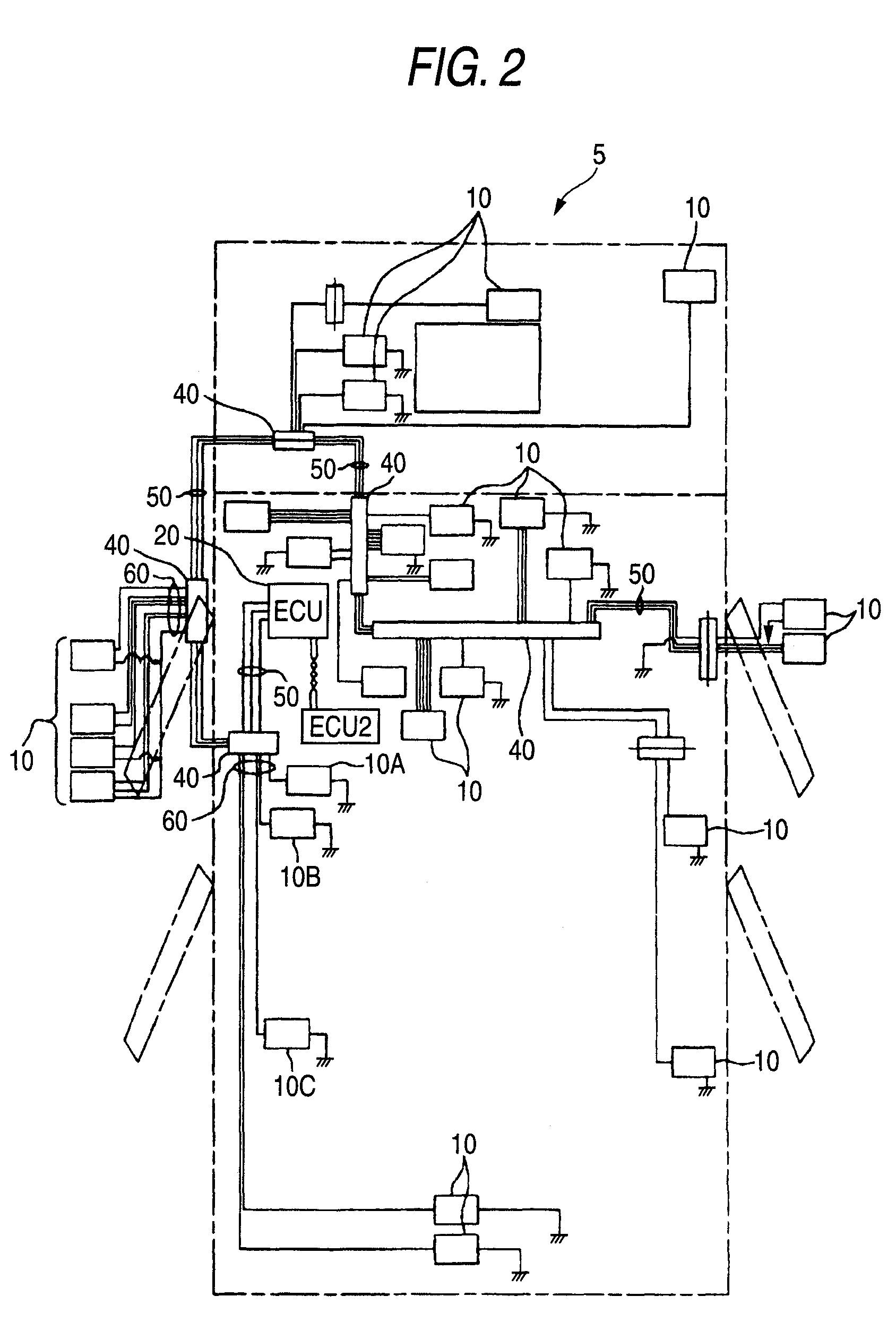
Referring to FIG. 2, an electronic device control system 1 is loaded on a vehicle 5. The electronic device control system 1 includes plural electronic devices 10 dottedly located on the vehicle 5, an electronic control unit (ECU) 20 for controlling the plural electronic devices 10 and a wire harness assembly 30 for communicatably connecting the plural electronic devices 10 and the ECU 20.

The plural electronic devices 10 are, for example, a door switch, a trunk switch, a door lock status switch, a door key control unit, a fuse junction box, a card slot unit, various status switches, a shift position switch, etc.

In this description, for simplicity of explanation, the explanation will be given of only electronic devices 10A, 10B and 10C shown in FIG. 3 among the plural electronic devi...


PUM


Abstract

A relay connector unit for communicating an electronic control unit with a plurality of electronic devices includes: a first connecting unit connected to the electronic control unit; a second connecting unit having a plurality of circuits connected to the electronic devices respectively; and a transferring unit connected to the first connecting unit and the second connecting unit. The transferring unit transmits first information received by the first connecting unit from the electronic control unit to at least one of the electronic devices through a corresponding circuit, on the basis of circuit identifying data included in first information, the circuit identifying data indicating the corresponding circuit to be transferred to or from. The transferring unit appends the circuit identifying data to second information received from one of the electronic devices through the corresponding circuit to transmit the second information to the electronic control unit through the first connecting unit.

Description

BACKGROUNDThis invention relates to a relay connector unit and an electronic device control system for controlling plural electronic devices by a single electronic control unit.A vehicle such as a passenger car or a track incorporates a great variety of electric devices such as a motor constituting an air conditioner, a wiper and a power window. In order to transmit electric power and control signals, wire harnesses are arranged. The wire harness has plural electric wires and a connector for housing terminal metal fittings connected to the terminals of the electric wires. The electric wire is a “sheathed wire” provided with a conductive core and an insulating sheath for covering the core.As the connector for the wire harness described above, used is a connector with a built-in electronic component (e.g. see Patent Reference 1), which incorporates circuit elements and others, in order to connect, via a network by data communication, an electronic device such as various actuators and ...

Claims


Application Information

Patent Timeline
Patent Type & Authority Patents(United States)
IPC IPC(8): G06F13/00H01R27/00H03K17/00
CPCH04L12/40032H04L12/403H04L12/4625B60R16/03
Inventor KANAZAWA, AKIYOSHIGOHARA, TAKASHI
Owner YAZAKI CORP
Why Eureka
Try Eureka