Constructing the large-span self-braced buildings of composite load-bearing wall-panels and floors

a technology of self-bracing and large-span floors, which is applied in the direction of structural elements, building components, construction materials, etc., can solve the problems of reducing the material consumption of the building. , to achieve the effect of increasing the moment of inertia of the cross-section, increasing the height of the steel web strip, and increasing the material consumption

Inactive Publication Date: 2011-03-08
MARA INST D O O
View PDF13 Cites 16 Cited by
  • Summary
  • Abstract
  • Description
  • Claims
  • Application Information

AI Technical Summary

Benefits of technology

[0009]Another feature of the panel is introduced steel tube, perpendicularly positioned and welded to steel webs between two concrete layers, defining the top of supports for bearing roof or floor construction of assembled units, allowing no eccentricity to occur. Reactions of supported roofs or floors units are thereby applied centrically to the steel tube which is anchored to both concrete layers at the top of the support. The steel tube is hence welded to both steel webs so that reactions are efficiently transmitted to both concrete layers avoiding in that way stress concentrations near supports. The new panel is initially (during assembly) mounted as a cantilever (finally as a cantilever panel with laterally attached top), with its down-end rigidly fixed to the socket of the foundation, as shown in FIG. 11. Consequently, the lower part of the panel has a full concrete cross-section at the length which is predetermined to entry the ground and foundation, below the ground floor-plate, as shown in FIGS. 4 and 8. That is where the largest bending moments occur so the full cross section suits. One more advantage of such a solid bottom is that the wall-panel can be easily erected being rotated about its bottom whereby some chips and crushes of the bottom edges can be accepted because the bottom of the panel finally comes into a socket being poured by concrete. The creep of the capillary moisture upwards the panel can be easily prevented by a suitable external non-hygroscopic coat up to the level of the surrounding terrain. The other possible way of breaking the moisture is inbuilt, moisture breaker. One more object of the invention is the method and apparatus for manufacturing such sort of panels in a rapid way making them suitable for mass production. The manufacturing method concerns with an additional device being part of the mold, providing moveable, temporary fixed bottom of the upper mold part for pouring the upper positioned concrete layer, as shown in FIGS. 9 and 10. The device comprises series of lateral sticks driven through holes in side forms of mould and through holes in steel webs of the panel. The rough-surface insulation strips are used to form the bottom of the upper mold being arranged over tops of bottom sticks, which, after concreting is done, rest one-side adhered to the concrete. After concrete of the upper concrete layer of the panel is hardened the moveable bottom is pulled aside. All the common features of the sandwich panels, that many other panels comprise, are not discussed here but only slightly mentioned because the goal of the present application was to obtain a stiff and load-bearing capable panel reliable to ensure stability of the building. Hence, until now, a reliable panel was disclosed which the real large span buildings can be constructed of.

Problems solved by technology

However, codes, usually limiting concrete covers of beams and columns do not consider such cases when reinforcement is confined so optimally between two layer meshes.
Such a use of wall panels would surely be restricted to some available range of application limited by bearing capabilities of the panel as well as with its slenderness or by building code requirements.
Otherwise, the depth of the wall panel would have to increase enormously what may cause different sorts of architectural problems making them unacceptable.
Exceeding that limit, even if ultimate strength and stability under vertical load were satisfactory such a construction doesn't satisfy limitations of lateral deflections of its slender panels when subjected to lateral loads such as earthquake or wind.
That is why many of earlier patented systems have failed being never widely used in practice.
However, large span low-rise assembled buildings are not constructed in that way because of the absence of possibility to form a proper, large stiff plane capable of connecting two distant wall-panel-assembled gables making them to serve as shear walls.
But as the height of the building increases slenderness of wall-panels grows up in a fast rate and the structure becomes unstable.

Method used


Image

  • Constructing the large-span self-braced buildings of composite load-bearing wall-panels and floors
  • Constructing the large-span self-braced buildings of composite load-bearing wall-panels and floors
  • Constructing the large-span self-braced buildings of composite load-bearing wall-panels and floors

Examples


Embodiment Construction

[0047]The description is set out under the following headings:

a) Wall panel

b) Floor element

c) Apparatus for manufacturing the wall-panel

d) Method of erecting a building

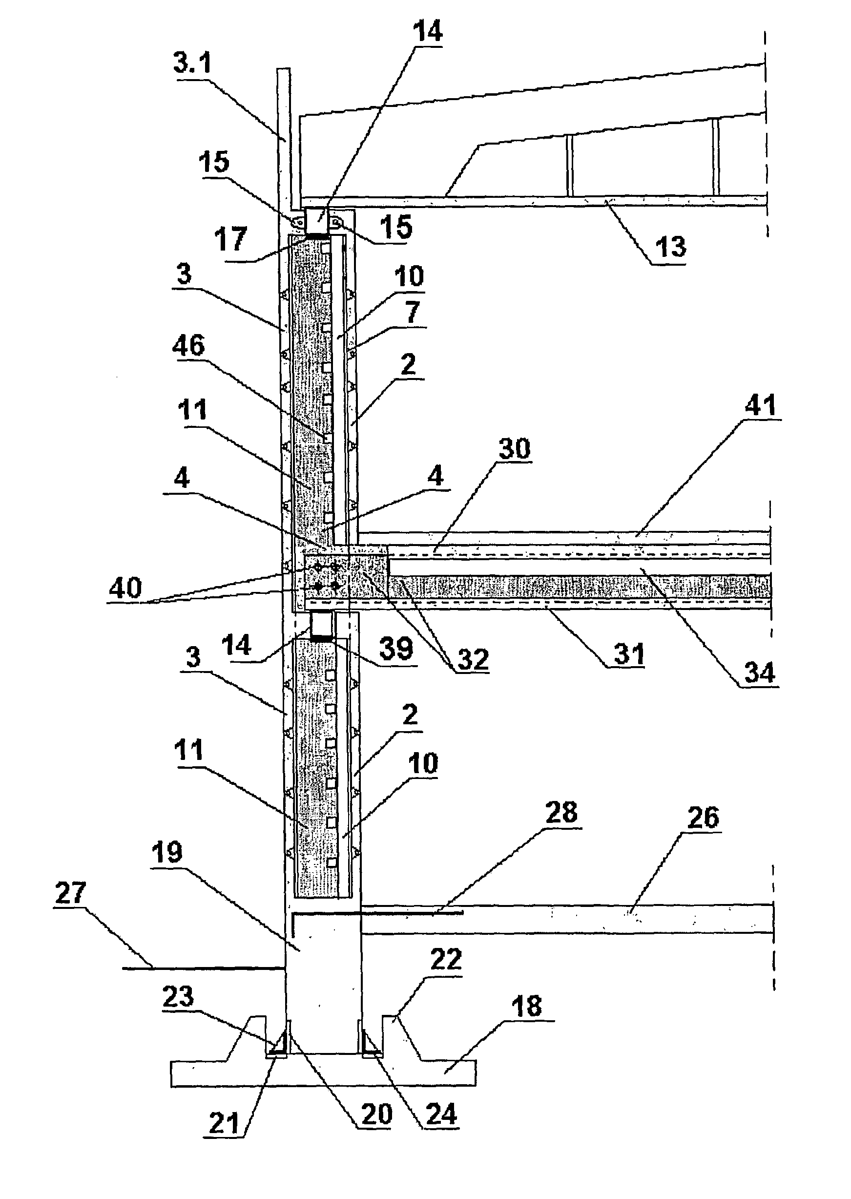
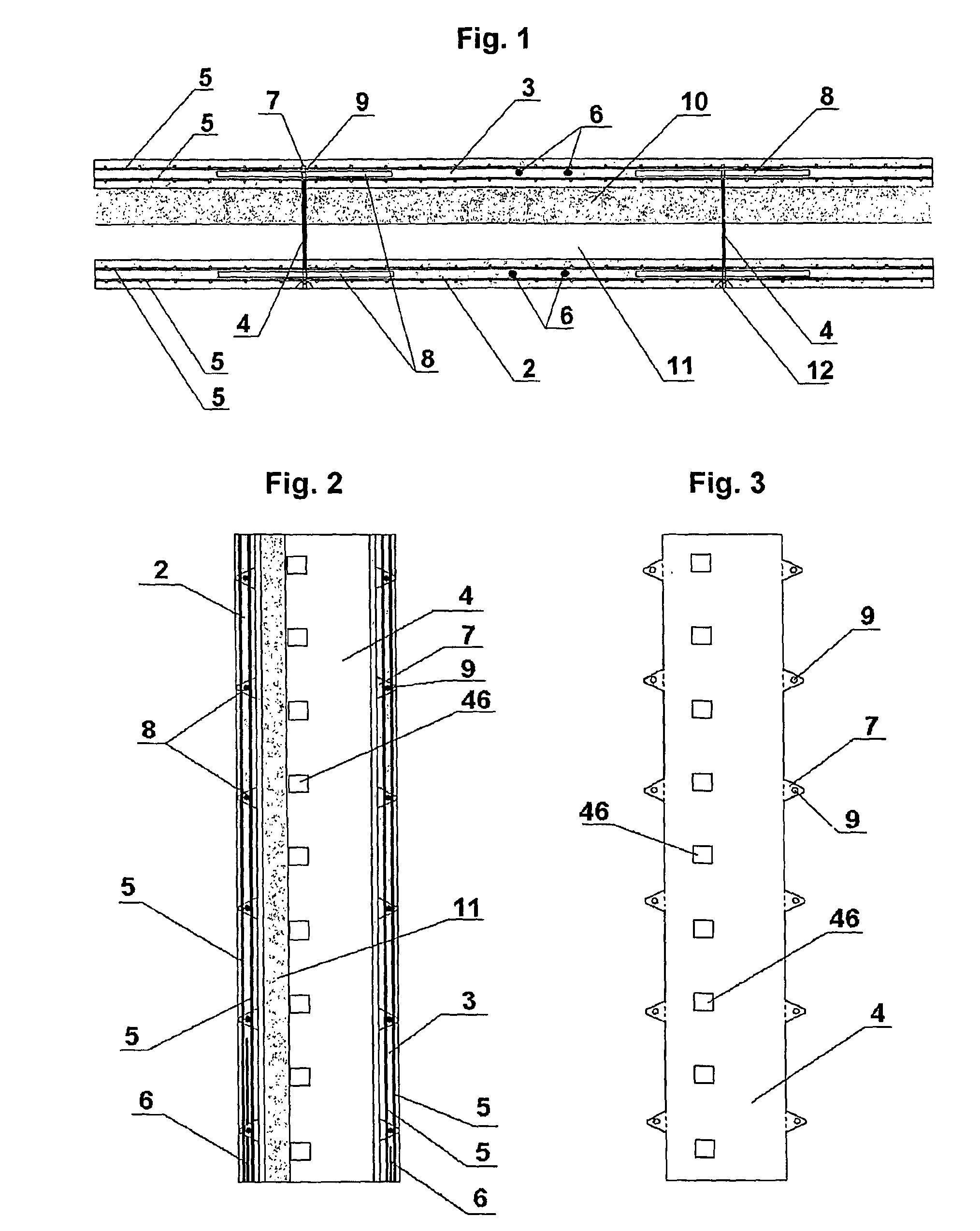
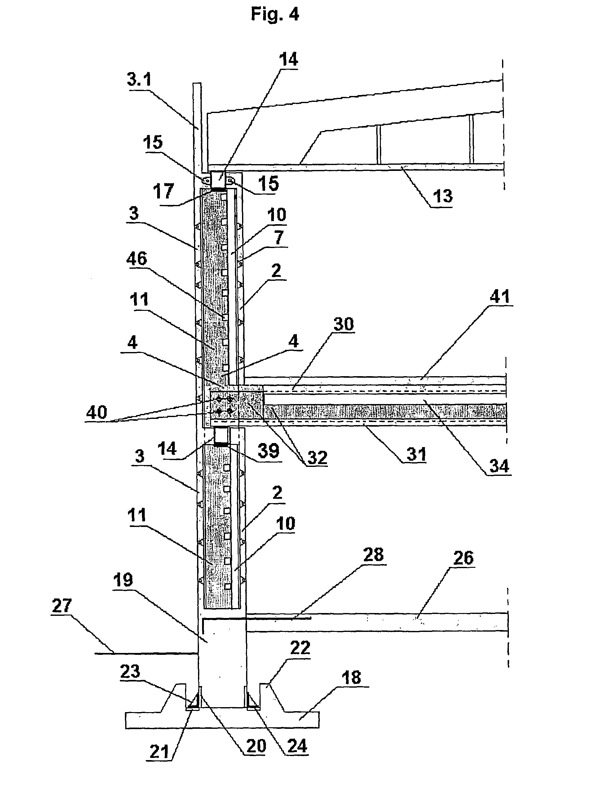
[0048]a) The composite wall-panel (1) shown by a cross section view in FIG. 1, by fragmentary longitudinal section in FIG. 2 and as a part of building in FIG. 4, comprises a cast concrete inner (2) and outer layer (3), both about 70 mm thick. The concrete elements are interconnected by at least two galvanized steel sheet strips (4) interposed into a gap between them. Both concrete panel elements (2) and (3) are substantially reinforced by two steel wire mesh layers (5). There's rather enough of free space between the two steel mesh layers in each concrete layer, across the width of the panel, whereto additional longitudinal reinforcing bars (6) can be placed, used for strengthening the panel, if necessary. Reinforcing bars can be replaced by pre-stressing wire-strands (completely or partially) dependably of the desire...


PUM


Abstract

Large span buildings without ordinary beams and columns are formed of vertical load-bearing composite wall-panels and composite floors, both including two concrete layers interconnected by steel strip webs. The stiff horizontal plane formed of assembled roof / ceiling units, supported by wall-panels, connected to both gables restrains transversal movement of longitudinally arranged wall-panels attached tops, bracing them simultaneously against sideway forces and lessening their buckling lengths. Floors, if any applied, being rigidly connected to the vertical panels additionally improve stability of the global structure. The structure, being braced in that way, behaves as a rigid box made of slender panels.

Description

TECHNICAL FIELD[0001]The present invention relates to the construction of floors of industrial or other similar buildings of prestressed, reinforced concrete and in particular some steel parts become integral parts of the structure. The field of the invention is described in IPC Classification E 04 B 1 / 00 that generally relates to constructions or building elements or more particularly group E 04 C 3 / 00 or 3 / 294.BACKGROUND ART[0002]The intention of the present invention is to establish a new assembling system for constructing large span buildings formed of composite vertical load-bearing wall-panels and composite floors whereby lateral bracing and stability of the structure is achieved using slender wall and floor elements only, needing no additional stabilizing construction. As a final task there was a challenge to construct the clear, large-span building with plane inner and outer surfaces, containing no ordinary beams and columns extending out of them. How it is done is described...

Claims


Application Information

Patent Timeline
Patent Type & Authority Patents(United States)
IPC IPC(8): E04B1/00E04B1/04E04B5/02E04C2/04E04C3/293E04C3/44
CPCE04B1/04E04B5/04E04B5/046E04C3/293E04C3/44E04C2/044E04C2/04
Inventor SKENDZIC, MILOVANSMRCEK, BRANKO
Owner MARA INST D O O
Why Eureka
Try Eureka