Cooling systems and electronic apparatus
a technology of electronic equipment and cooling system, which is applied in the direction of domestic cooling equipment, electric equipment casings/cabinets/drawers, instruments, etc., can solve the problems of complicated apparatus configuration and inability to introduce external air, and achieve efficient cooling of an electronic equipment group, low noise, and reduced temperature variation among electronic equipment installed in the data center
- Summary
- Abstract
- Description
- Claims
- Application Information
AI Technical Summary
Benefits of technology
Problems solved by technology
Method used
Image
Examples
embodiment 1
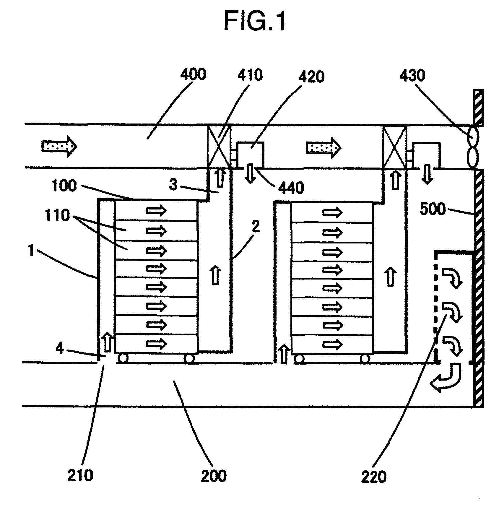
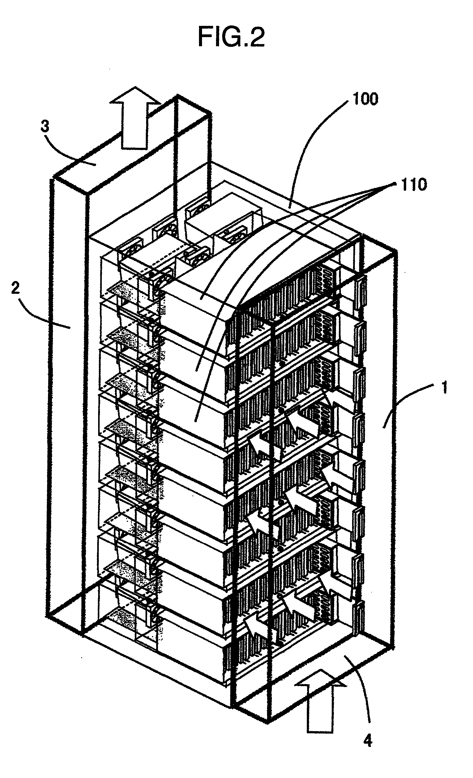
[0040]FIG. 1 is a schematic configuration view of a cooling system including one embodiment of the present invention. FIG. 2 is a perspective view of an electronic apparatus including the present embodiment.
[0041]In FIGS. 1 and 2, a cooling system of the present embodiment is configured by an electronics rack 100, an air conditioning area at below the floor level 200, an air conditioner 220, a ceiling air duct 400 and the like. The electronics rack 100 is configured by electronic equipment 110 in multiple layers installed in the rack. In the present embodiment, a 19-inch standard rack is adopted, and a plurality of fans not illustrated are provided in the electronic equipment 110 in the multiple layers installed in the rack. By the fans, cooling air is taken in from the front side of the rack and is exhausted from the rear side. Further, in the present embodiment, a front cover 1 is provided at the front surface of the electronics rack 100, and a back cover 2 is provided at the rear...
embodiment 2
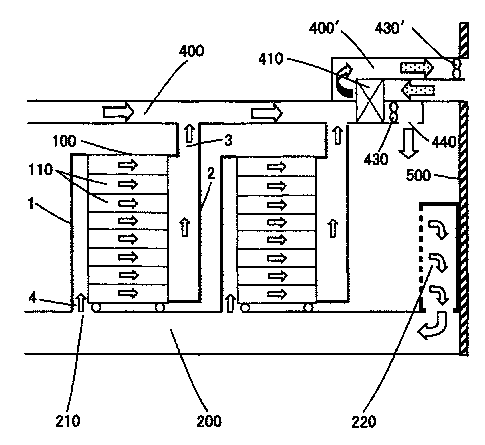
[0050]FIG. 3 is a schematic configuration view of a cooling system including a second embodiment of the present invention.
[0051]In FIG. 3, the cooling system is also configured by the electronics rack 100, the air conditioning area at below the floor level 200, the air conditioner 220, the ceiling air duct 400 and the like in the present embodiment. In the present embodiment, the flow path is divided into two flow paths that are the ceiling air duct 400 in which the indoor side air flows, and a ceiling air duct 400′ in which external air flows, and the heat exchanger 410 is provided between the two flow paths. In the case of FIG. 3, external air flows in from the lower right side of the wall 500, and is exhausted from the upper right side of the wall 500. The heat exchanger 410 is for gas, with one flow path being connected to the external air flowing inside the ceiling air duct 400′, and with the other flow path being connected to the indoor air flowing in the ceiling air duct 400....
embodiment 3
[0059]A third embodiment of the present invention is shown in FIG. 4.
[0060]FIG. 4 is a schematic general view of a cooling system in the present embodiment.
[0061]In FIG. 4, the cooling system is also configured by the electronics rack 100, the air conditioning area at below the floor level 200, the air conditioner 220, the ceiling air duct 400 and the like in the present embodiment. Further, the ceiling air duct 400 is divided into two flow paths that are an indoor side air flow 400a, and an external air flow 400a′, and the heat exchanger 410 is provided between the two flow paths.
[0062]In the present embodiment, a set of an ANC (Active Noise Control) device is incorporated in the vicinity of the ceiling blowing out opening 440 of the ceiling air duct 400 at the indoor air side. The ANC device of the present embodiment is configured by an error sensor 330, a noise sensor 320, a speaker 310, and an active noise controller 300. The ANC device calculates a signal in an opposite phase f...
PUM
 Abstract
Description
Claims
Application Information
 - R&D
- Intellectual Property
- Life Sciences
- Materials
- Tech Scout
- Unparalleled Data Quality
- Higher Quality Content
- 60% Fewer Hallucinations
Browse by: Latest US Patents, China's latest patents, Technical Efficacy Thesaurus, Application Domain, Technology Topic, Popular Technical Reports.
© 2025 PatSnap. All rights reserved.Legal|Privacy policy|Modern Slavery Act Transparency Statement|Sitemap|About US| Contact US: help@patsnap.com


