
Bonded metal components having uniform thermal conductivity characteristics

a technology of thermal conductivity and bonded metal, which is applied in the direction of application, baking vessels, soldering apparatus, etc., can solve the problems of thermal warpage and accelerated thermal degradation of non-stick surfaces, and achieve the effect of preventing sound metallurgical bonding

Inactive Publication Date: 2011-03-15
CLAD METALS
View PDF29 Cites 18 Cited by
  • Summary
  • Abstract
  • Description
  • Claims
  • Application Information

AI Technical Summary

Benefits of technology

The invention is a composite cookware made of aluminum, copper, and stainless steel layers with a heat-retardant metal core. The method involves bonding titanium or titanium alloy strips to aluminum or stainless steel layers using a stainless steel layer as a thermal barrier. The surfaces of the layers are mechanically abraded to clean them and expose bare metal. The stack is then heated at a specific temperature in an oxygen-containing atmosphere to bond the layers. The resulting cookware has a uniform heating across the inner surface and can be shaped into desired shapes. The invention also includes the use of a ferro-magnetic material for induction cooking and the option of a non-stick surface for easy cleaning.

Problems solved by technology

These hot spots not only are troublesome in cooking and ironing but they also cause an accelerated thermal degradation of the non-stick surface.
Even if no non-stick surface is present, localized hot spots are undesirable in cookware, since it leads to unequalized cooking.
First, due to the non-bonded graphite ply, slight air gaps most probably would be present between the graphite ply and the adjacent layers of aluminum and stainless steel which act as a thermal insulator by way of a barrier or film effect so as to lower the efficiency and uniformity of heat transfer across the interface.
In addition, due to the lack of metallurgical bonding between the aluminum and stainless steel layers along the cooking surface of the Woolf cookware, one would expect some thermal warping to occur by virtue of the difference in thermal expansion coefficients of aluminum and stainless steel.

Method used


Image

  • Bonded metal components having uniform thermal conductivity characteristics
  • Bonded metal components having uniform thermal conductivity characteristics
  • Bonded metal components having uniform thermal conductivity characteristics

Examples


Embodiment Construction

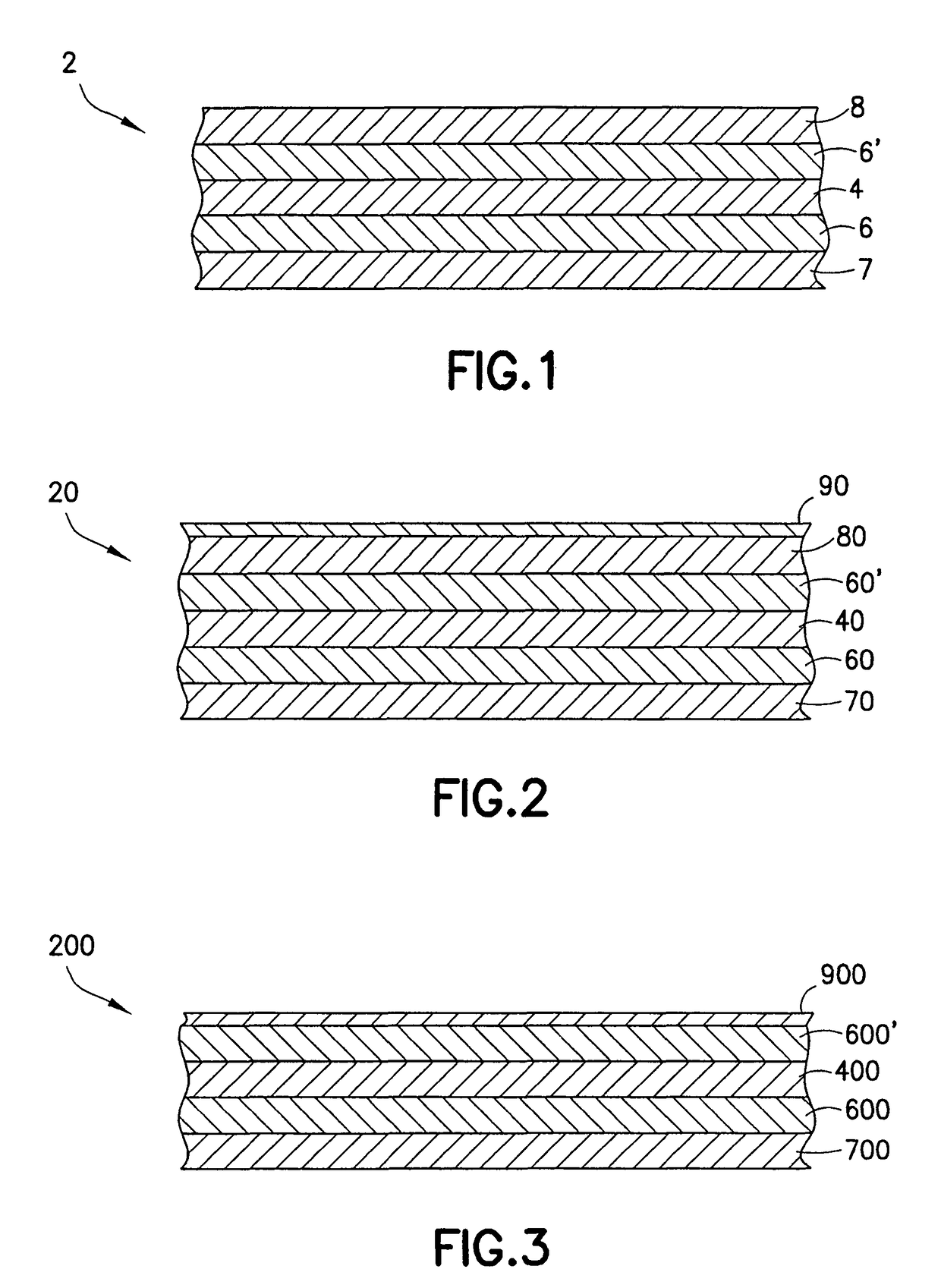
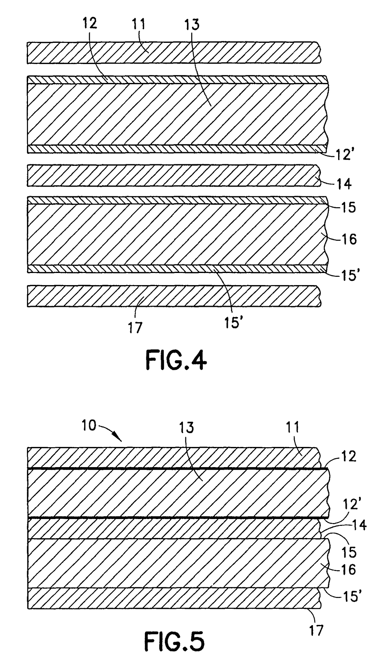
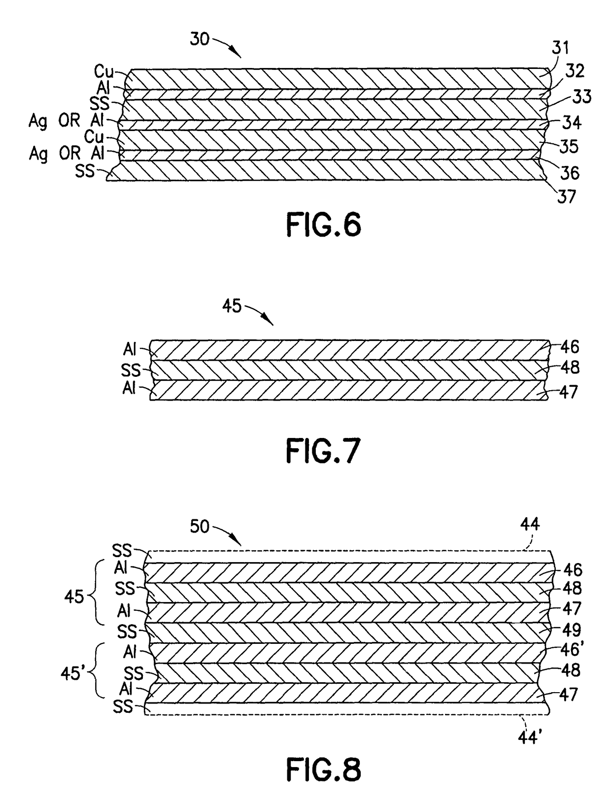
[0022]With reference now to the appended drawings, FIG. 1 schematically depicts, in cross section, one preferred embodiment of a bonded metal composite sheet 2 of the present invention. The composite sheet 2 is a multi-layered, rolled bonded construction comprising a thermal barrier layer 4 of a material having a lower coefficient of thermal conductivity than the other metal layers in the composite metal sheet 2. The presently preferred material for the lower thermal conductivity layer 4 is titanium or titanium alloy because of its relatively lower heat conductivity coefficient compared with the aluminum coupled with its light weight, which is comparable to aluminum. Stainless steel has a coefficient of heat conductivity similar to that of titanium and may be used for the layer 4. Stainless steel is less expensive than titanium but is heavier, adding to the weight of the cooking vessel. In the composite sheet 2 of FIG. 1, the titanium layer 4 is roll bonded on both sides between alu...


PUM

PropertyMeasurementUnit
temperatureaaaaaaaaaa
thickaaaaaaaaaa

Abstract

Cookware having improved uniform heat transfer over the entire cross section thereof, the cookware formed from a multi-layered composite metal having a layer of stainless steel roll bonded at or near the core of the composite to act as a thermal barrier and provide more uniform heat distribution on the cook surface. The stainless layer is roll bonded to layers of aluminum which, in turn, is roll bonded to layers of stainless steel or aluminum or copper. The layer of stainless steel adjacent to the cooking range may be a ferromagnetic grade of stainless steel if induction-type heating is desired. The cookware may include a non-stick surface applied thereto.

Description

CROSS-REFERENCE TO RELATED APPLICATIONS[0001]This is a continuation-in-part of co-pending application Ser. No. 11 / 199,397 filed Aug. 8, 2005, now U.S. Pat. No. 7,208,231, which is a divisional of application Ser. No. 10 / 608,898 filed Jun. 27, 2003, now U.S. Pat. No. 6,926,971, which claims the benefit of U.S. Provisional Application No. 60 / 392,312 filed Jun. 28, 2002, entitled “Bonded Metal Components Having Uniform Thermal Conductivity Characteristics”, all of which are incorporated by reference herein in their entireties.BACKGROUND OF THE INVENTION[0002]1. Field of the Invention[0003]The present invention relates generally to composite bonded metal cookware, griddle plate or a sole plate for an iron and, more particularly, to bonded composite metal cookware, griddle plate or a sole plate for an iron or the like, having at least one inner metal layer possessing a lower coefficient of thermal conductivity than the other metal layers of the composite so as to cause the heat to satura...

Claims


Application Information

Patent Timeline
Patent Type & Authority Patents(United States)
IPC IPC(8): B32B15/18B32B15/20A47J36/02
CPCA47J36/02B32B15/012Y10T428/12979Y10T428/12903Y10T428/12764Y10T428/1275Y10T428/12896Y10T428/12757
Inventor GROLL, WILLIAM A.
Owner CLAD METALS
Learn More