Socket and prosthesis for joint replacement

a joint replacement and socket technology, applied in the field of orthopaedics and repair, can solve the problems of large fraction of joint replacement surgeries failing, ball joints and load bearing structures are often damaged, and none of them meet the needs of an aging and increasingly overweight population, and achieve the effect of preventing bone loss

Inactive Publication Date: 2011-03-22
STINNETTE ALBERT
View PDF117 Cites 29 Cited by
  • Summary
  • Abstract
  • Description
  • Claims
  • Application Information

AI Technical Summary

Benefits of technology

One advantage of the socket and prosthesis for joint replacement is that the retention mechanism does not require additional steps in the surgical procedure. Another advantage is that no fasteners may be necessary to secure the retention mechanism. Yet another advantage is that the socket and ball unit is inserted as a unit, avoiding the introduction of detritus such as bone chips between the shell and the ball...

Problems solved by technology

Ball joints and load bearing structures are often damaged by disease, wear and fractures that require repair or replacement of these structures.
Several retention mechanisms have been developed that helped to secure load bearing structures and ball and socket joints; however, none of them meet the needs of an aging and increasingly overweight population.
A large fraction of joint replacement surgeries fail due to dislocation of the ball from the socket.
Various ...

Method used


Image

  • Socket and prosthesis for joint replacement
  • Socket and prosthesis for joint replacement
  • Socket and prosthesis for joint replacement

Examples


Embodiment Construction

The examples described and drawings rendered are illustrative and are not to be read as limiting the scope of the invention as it is defined by the appended claims. Many variations in the system, changes in specific components of the system and uses of the system will be readily apparent to those familiar with the area based on the drawings and description provided.

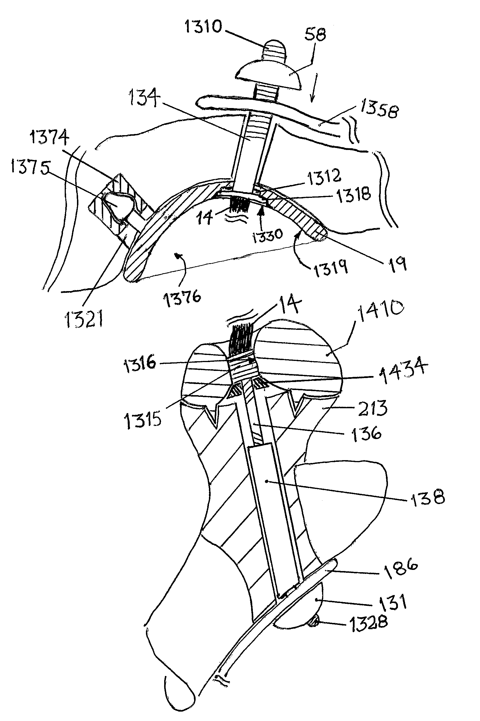
In one example, the attachment of the shell, itself, is made by a conventional process, which fixes the shell using lag screws to the bone of a patient. The shell may be located anatomically on a supporting structure or may be reversed and located on a long bone of the patient, such as done in some shoulder replacement procedures. In either alternative, a ball and shell unit is inserted, and the shell holding the ball is fixed to the underlying bone, while the ball is capable of articulated motion within the shell and is attached to a free end of a prosthesis fixed to another bone of the patient.

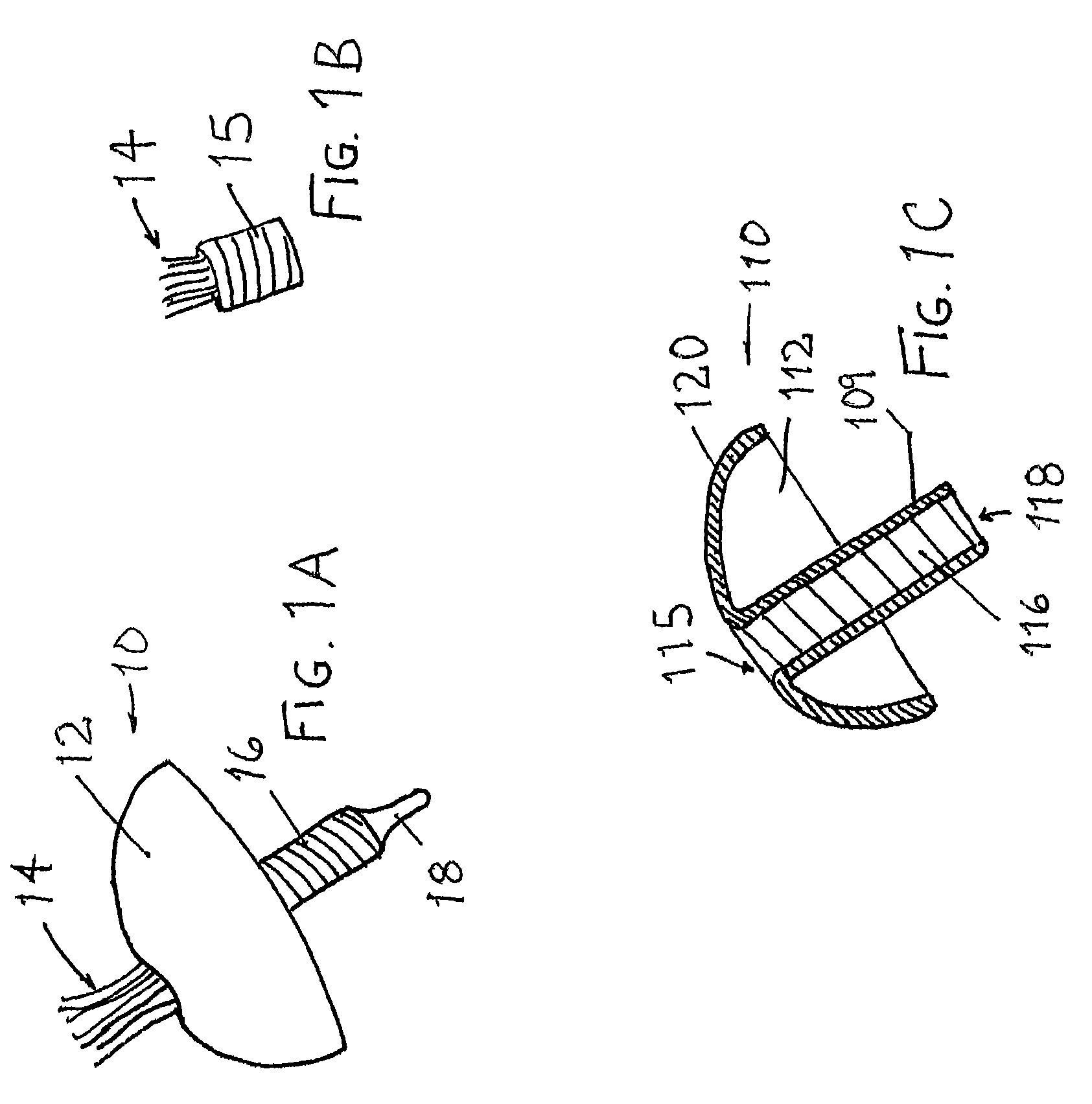
The example of FIG. 1A sho...


PUM


Abstract

A joint replacement prosthesis and procedure reduce the number of steps to complete a joint replacement. The joint replacement prosthesis comprises a ball and socket unit that fixes the ball in the socket prior to surgery. The unit is coupled to a bone structure in the patient and is coupled with a prosthesis that is fixed to another bone of the patient, such as a femoral implant fixed in a femur and providing a coupling at the end of a neck portion that is easily fit into a femoral head and acetabulum unit. A tether may be used to retain the ball in the socket and/or the ball may be retained by extension in the socket that do not restrict patient motion.

Description

FIELD OF THE INVENTIONThe field relates to orthopedics and repair of fractures and wear to load bearing bones and joints.BACKGROUNDBall joints and load bearing structures are often damaged by disease, wear and fractures that require repair or replacement of these structures. Several retention mechanisms have been developed that helped to secure load bearing structures and ball and socket joints; however, none of them meet the needs of an aging and increasingly overweight population. Many mechanisms for repair and replacement require unnecessary additional steps during surgery in order to secure and / or retain a prosthesis or to repair a fracture in a bone. FIG. 12 shows a prior art fixation device 54 comprising a capped end 52, a pointed end 56 and a ratchet connector 58 having spades 59 that mate with ridges 40 to adjust the length l between the capped end 52 and the connector 58 using a quick ratchet mechanism locks the spades 59 into the grooves 50 between the ridges 40. There is ...

Claims


Application Information

Patent Timeline
IPC IPC(8): A61F2/32
CPCA61F2/32A61F2/34A61F2/3603A61F2/3609A61F2/4003A61B17/746A61F2/08A61F2/30749A61F2/38A61F2002/30093A61F2002/30095A61F2002/30331A61F2002/30448A61F2002/30462A61F2002/30495A61F2002/3052A61F2002/30579A61F2002/30841A61F2002/3085A61F2002/30901A61F2002/3092A61F2002/3401A61F2002/3411A61F2002/3422A61F2002/347A61F2002/3611A61F2002/365A61F2002/4007A61F2002/4022A61F2002/4085A61F2210/0019A61F2210/0023A61F2220/0008A61F2220/0025A61F2220/0033A61F2220/005A61F2220/0075A61F2002/30092A61F2002/342A61F2002/30594A61F2002/305
Inventor STINNETTE, ALBERT
Owner STINNETTE ALBERT
Why Eureka
Try Eureka