Method and device for controlling motor, and image forming apparatus

a technology of image forming apparatus and motor, which is applied in the direction of electric controllers, ignition automatic control, instruments, etc., can solve the problems of power consumption increase, inability to change the current limit setting, and inability to achieve the effect of reducing efficiency

Inactive Publication Date: 2011-03-22
RICOH KK
View PDF22 Cites 15 Cited by
  • Summary
  • Abstract
  • Description
  • Claims
  • Application Information

AI Technical Summary

Benefits of technology

[0009]It is an object of the present invention to at least partially solve the problems in the conventional technology.

Problems solved by technology

However, a power consumption increases because of a current sensing resistor of the comparator, and thus the efficiency decreases.
Furthermore, in the conventional technologies, it is not possible to change setting of the current limit.
Moreover, the conventional motor control device costs due to the comparator and the increased number of control integrated circuits (IC) and pins for the comparator.

Method used


Image

  • Method and device for controlling motor, and image forming apparatus
  • Method and device for controlling motor, and image forming apparatus
  • Method and device for controlling motor, and image forming apparatus

Examples


first embodiment

[0051]A motor control device according to the present invention calculates a current flowing into a driver based on a rotation velocity of a motor, and controls a pulse-width modulation (PWM) drive signal so that the calculated current is kept below a current limit.

[0052]The motor control device according to the first embodiment controls a motor included in an image forming apparatus, such as a digital multifunction peripheral (MFP) including a copy function, a FAX function, a printer function, a scanner function, an image delivering function for delivering an image of a document scanned by the scanner function or an image input by the printer function or the FAX function, and the like to the outside.

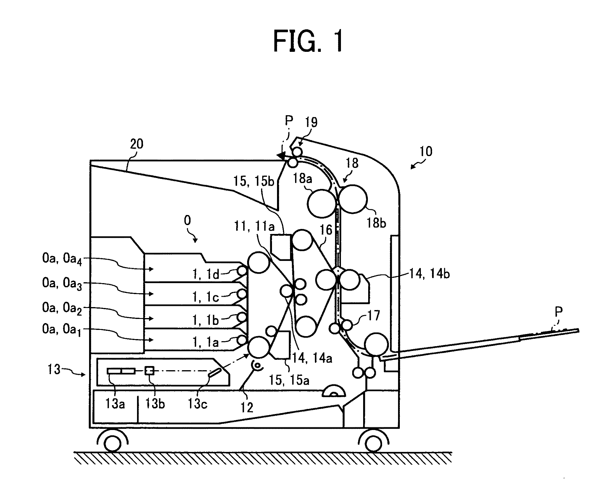
[0053]FIG. 1 is a schematic diagram of an image forming apparatus 10 to which the motor control device according to the first embodiment is applied. As shown in FIG. 1, the image forming apparatus 10 includes a photosensitive belt 11, a charging unit 12, a latent-image forming unit 13, ...

second embodiment

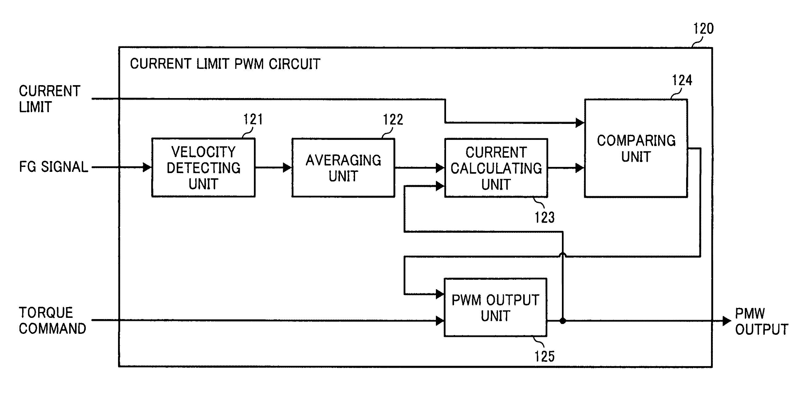
[0116]FIG. 16 is a block diagram of a current limit PWM circuit 1620 included in the motor control device according to the As shown in FIG. 16, the current limit PWM circuit 1620 includes the velocity detecting unit 121, the averaging unit 122, the current calculating unit 123, the comparing unit 124, a PWM output unit 1625, a timer unit 1626, and a max-duty determining unit 1627. The portions identical to those in FIG. 12 are denoted with the same reference numerals, and the description of those portions is omitted.

[0117]The timer unit 1626 measures a time. The max-duty determining unit 1627 determines to output a predetermined initial value as a duty cycle of a PWM signal from a start-up time of the motor (an initial time) to a predetermined time “ts” based on the time measured by the timer unit 1626.

[0118]By the time ts, the PWM output unit 1625 outputs the initial value determined by the max-duty determining unit 1627 as a PWM output value. After the time ts, in the same manner...

third embodiment

[0125]FIG. 19 is a graph for explaining a relationship between a rise of a current and a rise of a rotation velocity of the motor after the motor start-up. As shown in FIG. 19, when a voltage is applied to the motor, an electrical rise time “te” of the current is significantly shorter than a mechanical rise time “tm” of the rotation velocity of the motor in general. In the third embodiment, it is configured to change the initial value of a duty cycle of a PWM signal by each predetermined time interval in response to both of the electrical rise time te and the mechanical rise time tm.

[0126]FIG. 20 is a graph for explaining an example of a duty cycle of a PWM signal output from a current limit PWM circuit of the motor control device according to the third embodiment. As shown in FIG. 20, from the motor start-up to a time “t1” corresponding to a rise delay time due to an L component of a coil, a PWM signal indicating a duty cycle of 100% is output. When the current electrically rises u...


PUM


Abstract

A control unit controls a drive signal for determining a voltage to be supplied to the motor. A drive unit drives the motor by applying a current corresponding to the voltage determined based on the drive signal to the motor. The control unit includes a velocity detecting unit that detects a rotation velocity of the motor and an output unit that outputs the drive signal corresponding to a voltage with which a current lower than a predetermined current limit is applied to the motor, based on the rotation velocity of the motor detected by the velocity detecting unit.

Description

CROSS-REFERENCE TO RELATED APPLICATIONS[0001]The present application claims priority to and incorporates by reference the entire contents of Japanese priority document 2007-047646 filed in Japan on Feb. 27, 2007. The present application incorporates by reference the entire contents of Japanese document 2006-262975 filed in Japan on Sep. 27, 2006.BACKGROUND OF THE INVENTION[0002]1. Field of the Invention[0003]The present invention relates to a technology for limiting an electric current applied to a motor driver within a tolerance.[0004]2. Description of the Related Art[0005]A conventional method for protecting a motor driver employs detection of a temperature of the driver or detection of a drive current applied to the driver to prevent a flow of an overcurrent into the driver. According to a motor control device disclosed in Japanese Patent Application Laid-open No. 2005-80349, an overcurrent protecting circuit and a heat protecting circuit are included in an inverter circuit to pr...

Claims


Application Information

Patent Timeline
Patent Type & Authority Patents(United States)
IPC IPC(8): H02P7/29
CPCG03G15/5008H02P23/0063H02P2205/01H02P2205/05H02P23/20
Inventor KOIKE, TAKAHISA
Owner RICOH KK
Why Eureka
Try Eureka