Antenna and method for steering antenna beam direction

a technology of antenna beam and beam direction, applied in the field of wireless communication, can solve the problem of prohibitive effect of effective implementation of such complex antenna array

Active Publication Date: 2011-03-22
KYOCERA AVX COMPONENTS (SAN DIEGO) INC
View PDF17 Cites 148 Cited by
  • Summary
  • Abstract
  • Description
  • Claims
  • Application Information

AI Technical Summary

Benefits of technology

[0007]In one embodiment of the present invention, the antenna includes a first parasitic element and a first active tuning element associated with the parasitic element, wherein the parasitic element and the active element are positioned to one side of the main antenna element, a second parasitic element and a second active tuning element associated with the second parasitic element. The second parasitic element and the second active tuning element are positioned below the main antenna element. In one embodiment, the second parasitic and active tuning elements are used to tune the frequency characteristic of the antenna, and in another embodiment, the first parasitic and active tuning elements are used to provide beam steering capability for the antenna.

Problems solved by technology

But effective implementation of such complex antenna arrays may be prohibitive due to size constraints associated with mobile devices.

Method used


Image

  • Antenna and method for steering antenna beam direction
  • Antenna and method for steering antenna beam direction
  • Antenna and method for steering antenna beam direction

Examples


Embodiment Construction

[0037]In the following description, for purposes of explanation and not limitation, details and descriptions are set forth in order to provide a thorough understanding of the present invention. However, it will be apparent to those skilled in the art that the present invention may be practiced in other embodiments that depart from these details and descriptions.

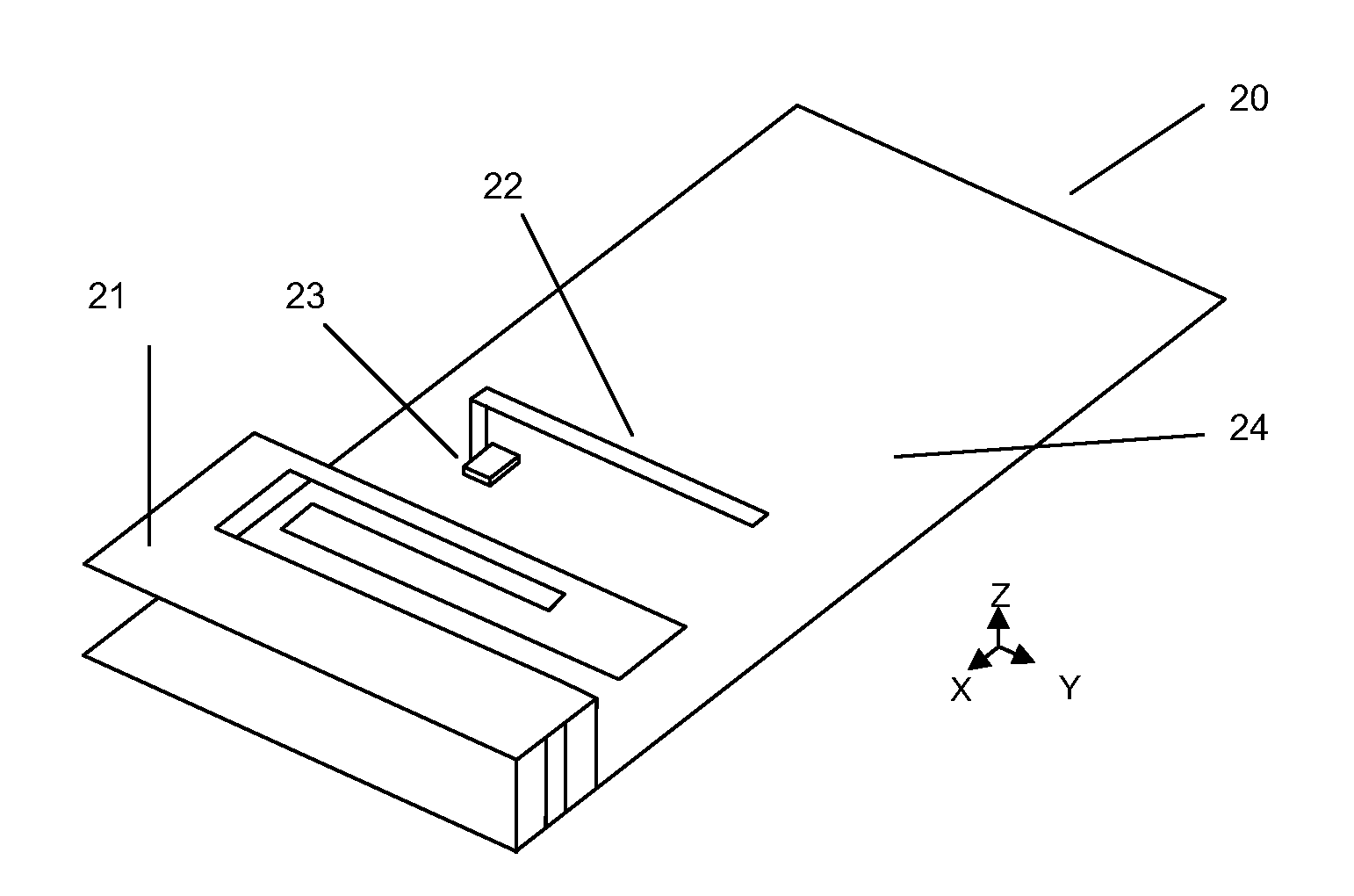
[0038]One solution for designing more efficient antennas with multiple resonant frequencies is disclosed in co-pending U.S. patent application Ser. No. 11 / 847,207, where an Isolated Magnetic Dipole™ (IMD) is combined with a plurality of parasitic and active tuning elements that are positioned under the IMD. With the advent of a new generation of wireless devices and applications, however, additional capabilities such as beam switching, beam steering, space or polarization antenna diversity, impedance matching, frequency switching, mode switching, and the like, need to be incorporated using compact and efficient antenna struct...


PUM


Abstract

An antenna comprising an IMD element, and one or more parasitic and active tuning elements is disclosed. The IMD element, when used in combination with the active tuning and parasitic elements, allows antenna operation at multiple resonant frequencies. In addition, the direction of antenna radiation pattern may be arbitrarily rotated in accordance with the parasitic and active tuning elements.

Description

[0001]Co-pending U.S. patent application Ser. No. 11 / 847,207, filed Aug. 20, 2007, entitled “Antenna With Active Elements,” and co-pending U.S. patent application Ser. No. 11 / 840,617, filed Aug. 17, 2007, entitled “Antenna with Near Field Deflector,” each of which is assigned to the assignee of this application, are incorporated herein by reference in their entirety for all purposes.FIELD OF INVENTION[0002]The present invention relates generally to the field of wireless communication. In particular, the present invention relates to antennas and methods for controlling radiation direction and resonant frequency for use within such wireless communication.BACKGROUND OF THE INVENTION[0003]As new generations of handsets and other wireless communication devices become smaller and embedded with more and more applications, new antenna designs are required to address inherent limitations of these devices and to enable new capabilities. With classical antenna structures, a certain physical vo...

Claims


Application Information

Patent Timeline
Patent Type & Authority Patents(United States)
IPC IPC(8): H01Q9/00
CPCH01Q1/243H01Q9/0442H01Q9/0421H01Q3/00H01Q5/385H01Q3/44
Inventor ROWSON, SEBASTIANDESCLOS, LAURENTSHAMBLIN, JEFFREY
Owner KYOCERA AVX COMPONENTS (SAN DIEGO) INC
Why Eureka
Try Eureka