Wind turbine blades with vortex generators

a technology of wind turbine blades and vortex generators, which is applied in the direction of wind motors with parallel air flow, non-positive displacement fluid engines, liquid fuel engine components, etc., can solve the problems of reducing the power production of wind turbines, the drag coefficient of blades, etc., and achieves the effect of reducing extreme loads, increasing chords, and increasing extreme loads

Active Publication Date: 2011-03-29
VESTAS WIND SYST AS
View PDF15 Cites 47 Cited by
  • Summary
  • Abstract
  • Description
  • Claims
  • Application Information

AI Technical Summary

Benefits of technology

[0029]A rotor with ultra low solidity operating with ultra high lift coefficients provides a possibility for a load reduction or / and more productive rotor with equal loads. An important issue in design of wind turbine blades is the resistance towards fatigue damage. In general, the fatigue is driven by the chord size, i.e. the larger the chord, the higher the fatigue loads on the blade. Furthermore, the vibrations arising in the blade in case of stall also increase the fatigue damages. It is therefore a considerable advantage of the present invention that despite the blade is operated with a higher design angle of attack AoA the fatigue characteristic of the blade is improved, mainly due to the reduction in chord length.
[0030]Extreme wind gusts with wind speeds up to 70 m / s generate extreme loads on the wind turbine. During extreme wind speeds the wind turbine rotor is idling, i.e. rotating slowly or is stopped with the blades in stop position and without power production. The magnitude of the extreme loads in such situations is depending on the chord length of the rotor blades, i.e. the larger the chord, the higher the extreme loads. It is therefore also a considerable advantage of the present invention that extreme loads are reduced by the slender blade design.
[0031]The principle of this aspect of the present invention is the use of one or preferably multiply rows of micro (or sub boundary layer) vortex generators attached to at least a part of the whole span of the blade, in a preferred embodiment along an outer half part of the blade, and in a preferred embodiment of the invention in combination with Gurney Flaps generating a very high lift coefficient CL with a relative gentle stall at very high angle of attack. The very high lift coefficient CL can reduce the necessary blade area and loads or / and increase the length of the blade and maintain the original loads with higher production.
[0032]When this furthermore is combined with the use of Gurney Flaps at the inboard part of the blade (such as the inner 10-50% of the blade radius as measured from the hub centre) to make a wind turbine blade of extreme slenderness.
[0033]Thus, the present invention relates also to a wind turbine rotor having at least two blades, each blade comprising a first row of vortex generators arranged in the longitudinal direction of the blade on a suction side (also called the leeward side) thereof and provided along at least 10% of the longitudinal extend of the blade and preferably along substantially all of the outer half part of the blade, wherein the height of said vortex generators in a direction away from the blade surface on which it is provided is within the range of 0.1% to 1% of the chord length, preferably within the range of 0.15% to 0.35% of the chord length as measured at the longitudinal position where the vortex generators are provided.
[0034]The combined radius specific solidity (Solr) of the rotor is

Problems solved by technology

The fact that vortex generators increases the drag coefficient of the blade and thus reduces the power production of the wind turbine delimits the actual use of vortex generators on wind turbine blades.

Method used


Image

  • Wind turbine blades with vortex generators
  • Wind turbine blades with vortex generators
  • Wind turbine blades with vortex generators

Examples


Embodiment Construction

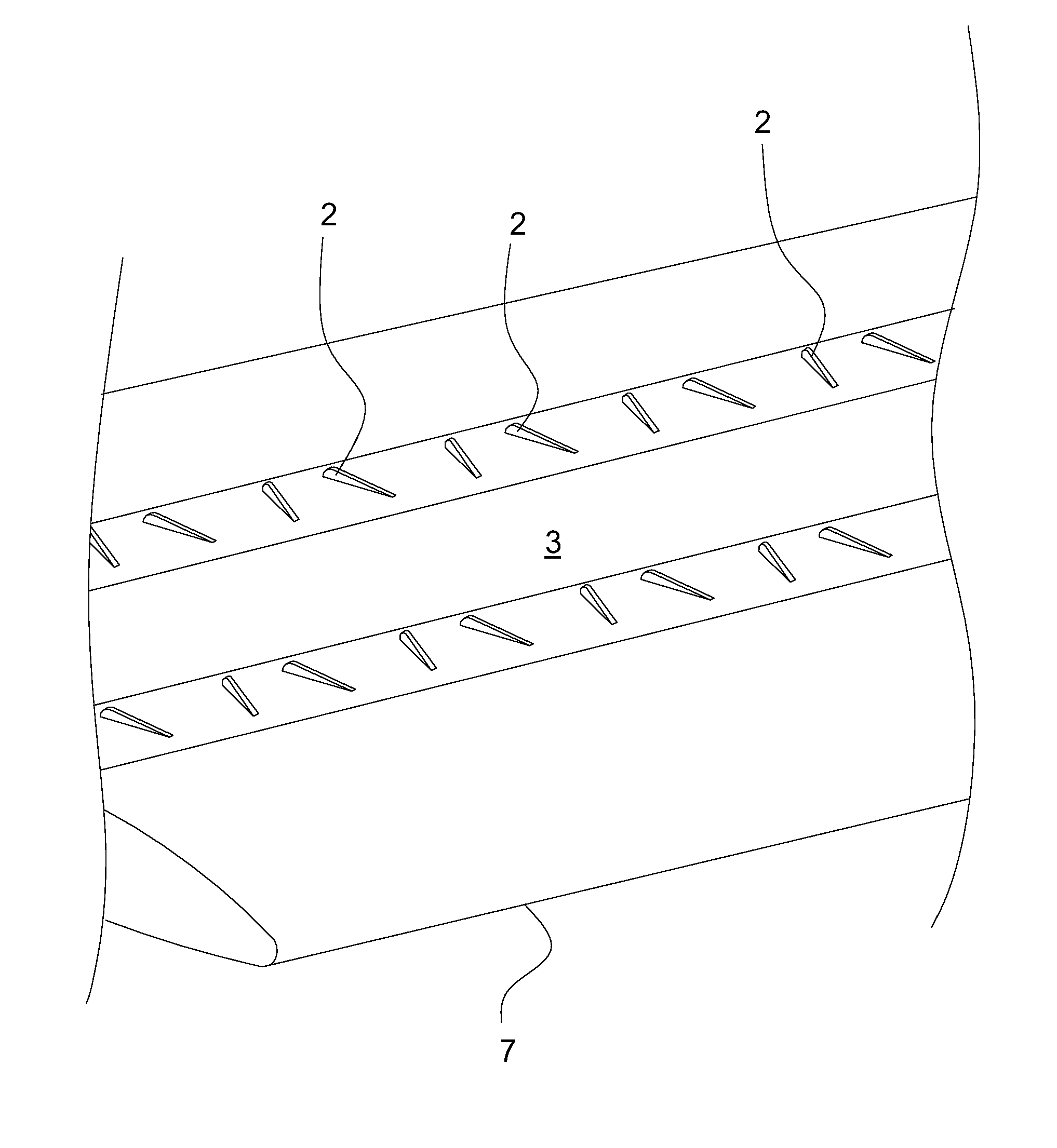
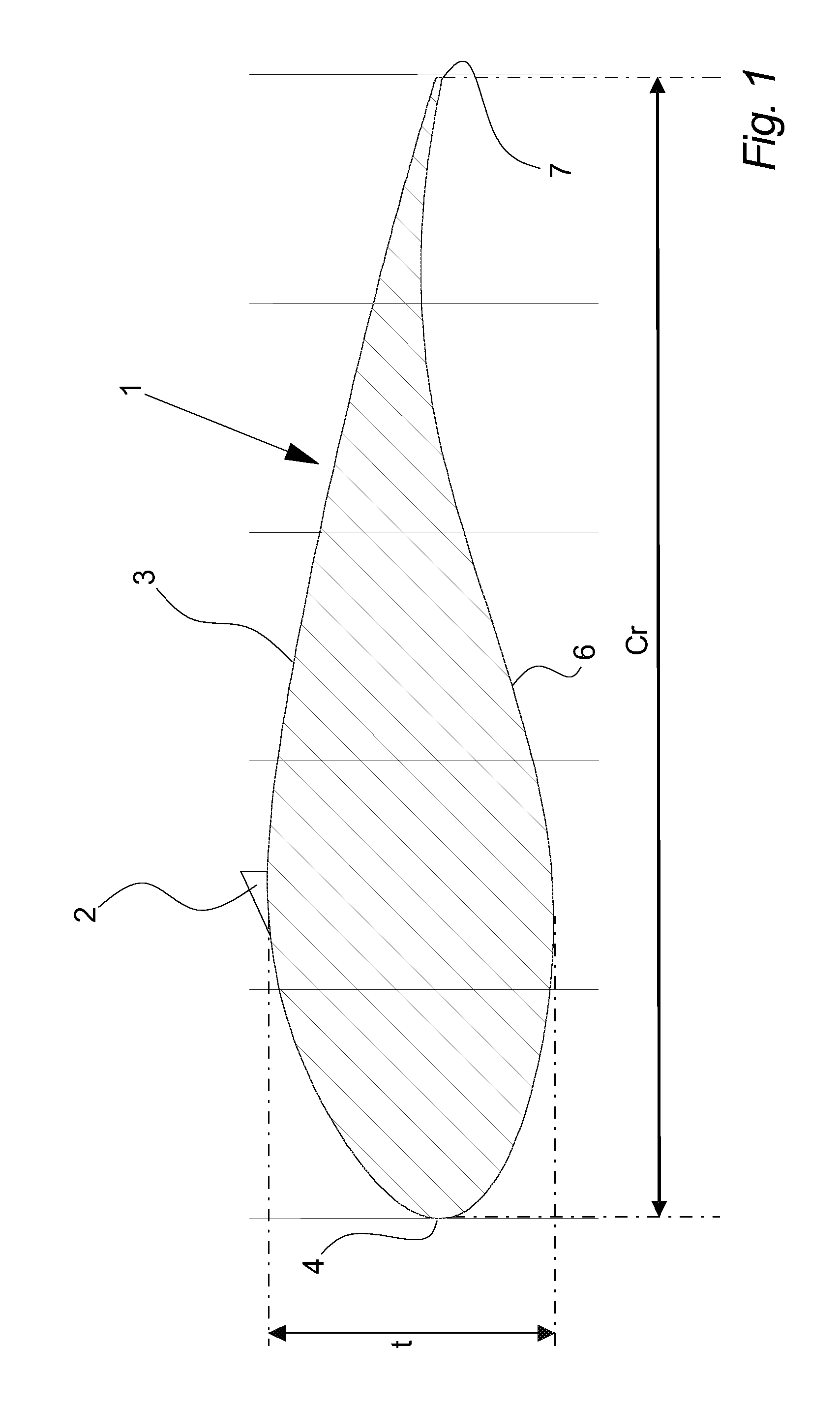
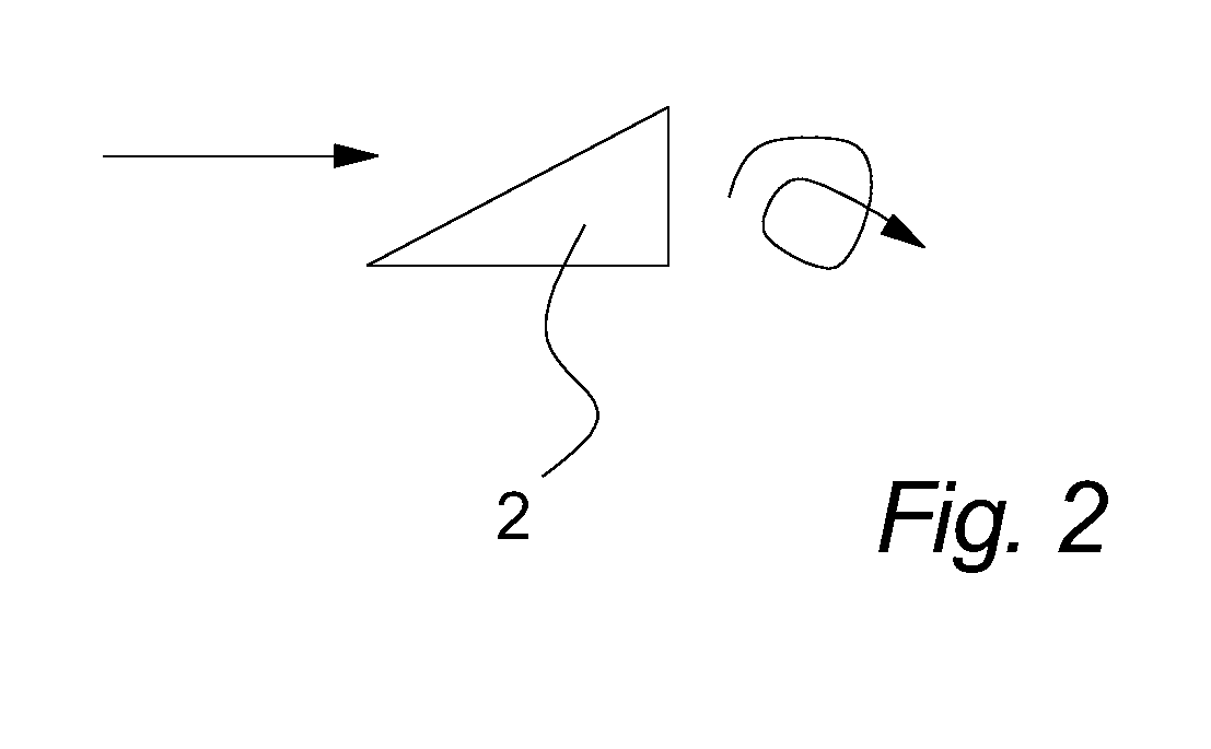
[0125]The principle of the preferred vortex generators is a delta shaped plate attached substantially orthogonal to the blade surface at the suction side (leeward side) of the wind turbine blade as shown in FIG. 1 depicting a cross-section of a blade 1 with a vortex generator 2 arranged on the suction side 3 of the blade 1 at a position of 30% of the chord length cr downstream of the leading edge 4 of the blade 1. The thickness t of the profile is also indicated. Other types of vortex generators than the ones discussed in this description may also be applied, please refer to the enclosed lists of references regarding vortex generators.

[0126]The vortex generators 2 induces vortices in the boundary layer substantially parallel to the direction of the flow over the blade and the vortices increases the kinetic energy of the airflow closest to the surface of the blade by transporting air of a higher velocity from the outer of the boundary layer down to the near surface region, thereby re...


PUM


Abstract

An advantageous new design of a wind turbine blade and rotor is obtained by providing one, two or more parallel rows of sub-boundary layer vortex generators, whereby a blade is obtained, which is resistant to stall and provides for a high maximum lift coefficient CL,max of the blades and a slender blade design, a low socalled radius specific solidity of the rotor. The very high lift coefficient CL can reduce the necessary blade area and loads or / and increase the length of the blade and maintain the original loads with higher production. The row or rows of sub-boundary layer vortex generators are in a preferred embodiment of the invention provided in combination with Gurney Flaps generating a very high lift coefficient CL with a relative gentle stall at very high angle of attack.

Description

CROSS-REFERENCE TO RELATED APPLICATIONS[0001]The present application is a continuation of pending International patent application PCT / DK2008 / 000103 filed on Mar. 13, 2008 which designates the United States and claims priority from Danish patent application PA 2007 00431 filed on Mar. 20, 2007, the content of which is incorporated herein by reference.FIELD OF THE INVENTION[0002]The present invention relates to wind turbine blades and a wind turbine rotor wherein the provision of vortex generators on the blades is used to obtain an advantageous new design of a rotor.BACKGROUND OF THE INVENTION[0003]The use of vortex generators for reduction of tendency to separation of the air flow on aircraft wings has long been well-known in the art, and an example is given in U.S. Pat. No. 4,354,648 disclosing a aircraft wing having two or three rows of low-profile vortex generators extending from the suction side surface e.g. 10-20% of the thickness of the boundary layer.[0004]Application of vort...

Claims


Application Information

Patent Timeline
Patent Type & Authority Patents(United States)
IPC IPC(8): B64C11/18
CPCF03D1/0641F05B2240/122F05B2240/32F05B2260/96Y02E10/721Y02E10/72Y02P70/50F05B2240/305F05B2240/3062
Inventor GODSK, KRISTIAN BALSCHMIDT
Owner VESTAS WIND SYST AS
Why Eureka
Try Eureka