Ring coil motor

a technology of ring coil motor and ring coil, which is applied in the direction of instruments, horology, and magnetic circuits characterised by magnetic materials, can solve the problems of complex design of electrical machines such as these, and achieve the effect of simple and cost-effective manufacturing

Inactive Publication Date: 2011-03-29
SIEMENS AG
View PDF17 Cites 16 Cited by
  • Summary
  • Abstract
  • Description
  • Claims
  • Application Information

AI Technical Summary

Benefits of technology

[0029]A ring coil motor design such as this has the advantage that the secondary part has no active means for producing a magnetic field. The secondary part has only a means for guiding magnetic fields, and is therefore simple and cost-effective to manufacture. A ring coil motor according to the invention is particularly highly suitable for electric motors with a large number of poles, that is to say motors whose number of pole pairs is p>7 and for combination drives, that is to say drives which have both a linear drive and a rotating drive.

Problems solved by technology

The design of an electrical machine such as this is very complex, since both the primary part and the secondary part have to have means for producing magnetic fields.

Method used


Image

  • Ring coil motor
  • Ring coil motor
  • Ring coil motor

Examples


Embodiment Construction

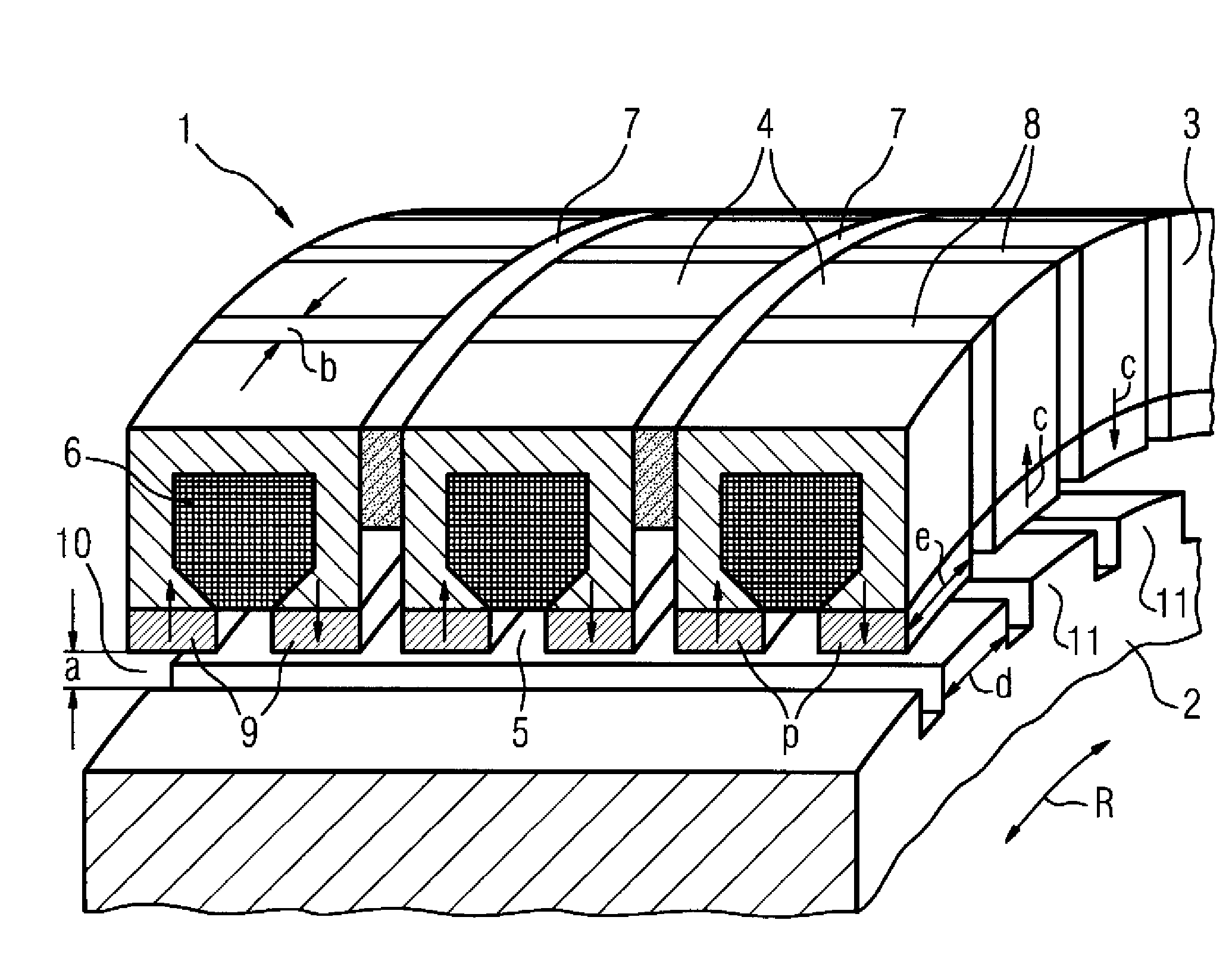
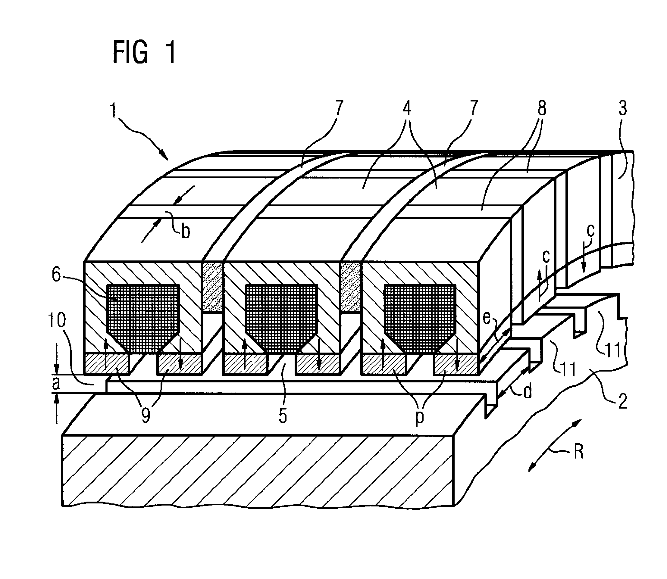
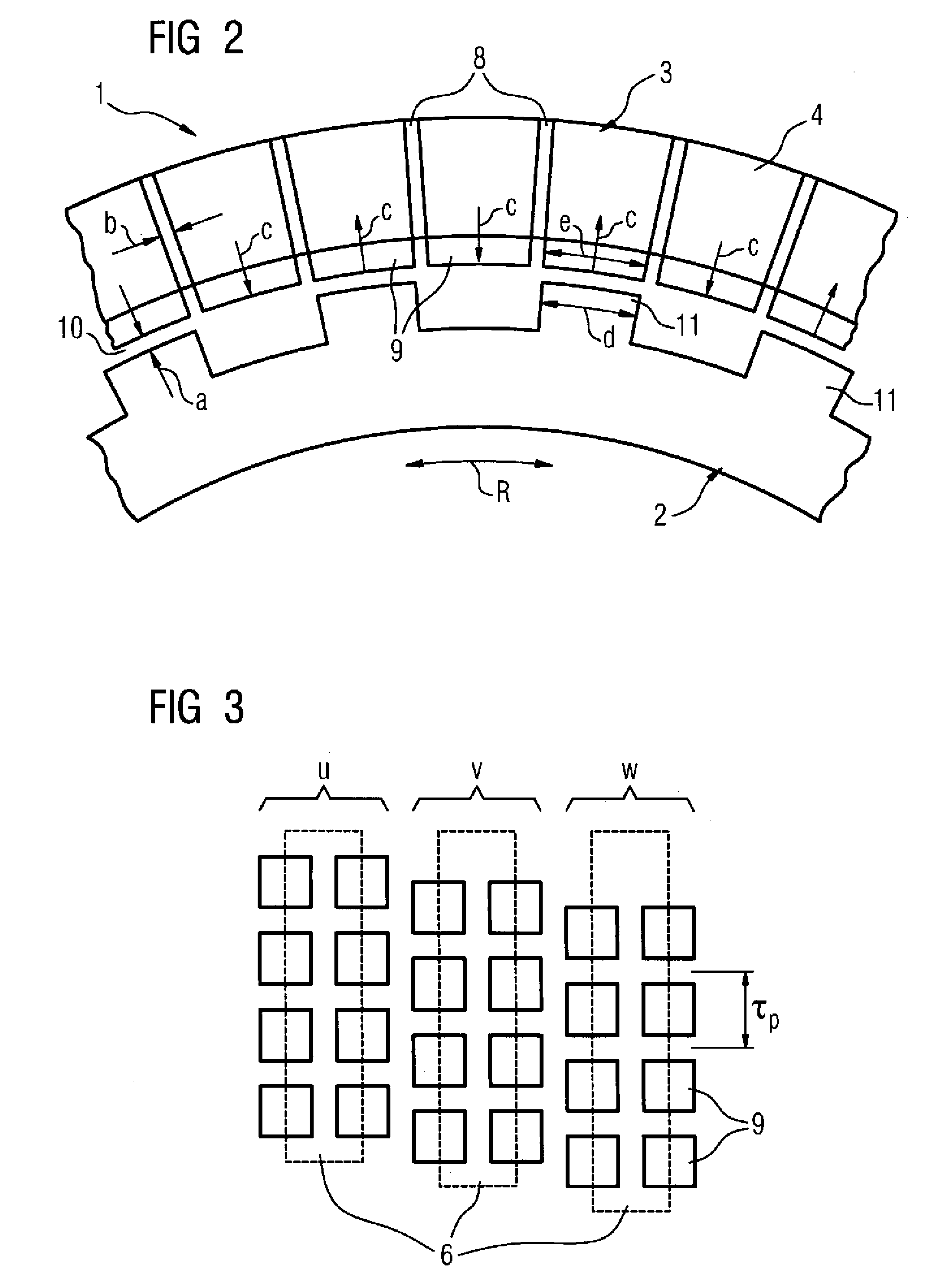
[0036]FIG. 1 shows a perspective partial view of the ring coil motor 1 according to the invention in an embodiment as a rotating ring coil motor, whose method of operation corresponds to that of a three-phase synchronous machine with permanent-magnet excitation. The ring coil motor 1 has the rotor 2 (secondary part) and the stator 3 (primary part). The stator 3 has three ring coils 6, which are arranged axially one behind the other around the rotor 2. By way of example, the ring coils 6 are produced from a copper (Cu) winding. Each ring coil 6 is intended for one phase u, v, w of a three-phase power supply system. Each ring coil 6 is located in a coil holder 4, which surrounds the ring coil and has an opening 5 towards the rotor 2. The coil holders 4 are used for arrangement of the ring coils 6. Furthermore, the radially magnetized permanent magnets 9 are arranged on the coil holders 4. The permanent magnets 9 are arranged on that side of the coil holder 4 which is opposite the roto...


PUM


Abstract

The invention relates to a ring coil motor (1, 20) with a primary part (3, 21) and a secondary part (2, 22), wherein the primary part (3, 21) has a ring coil (6, 25) and permanent magnets (9, 27).

Description

BACKGROUND OF THE INVENTION[0001]The invention relates to a ring coil motor having a primary part and a secondary part.[0002]Electrical machines have a primary part and a secondary part. In particular, the primary part is opposite the secondary part. The primary part is intended for electric current to flow through. The secondary part has, for example, permanent magnets or windings through which a current can flow. In the case of electrical machines such as this, in consequence, both the primary part and the secondary part have active magnetic means for generation of magnetic fields. The magnetic fields which are produced by the primary part and the secondary part interact with one another, and therefore produce a torque.[0003]DE 103 29 651 A1 discloses a linear motor with a ring winding, wherein the primary part is formed from a plurality of laminated cores and the laminated cores are surrounded by circumferential coils, also referred to as ring coils. In order to produce a second ...

Claims


Application Information

Patent Timeline
Patent Type & Authority Patents(United States)
IPC IPC(8): H02K17/00
CPCH02K16/04H02K21/44H02K41/033H02K1/02H02K2213/03
Inventor VOLLMER, ROLF
Owner SIEMENS AG
Why Eureka
Try Eureka