Methods and systems for decorating bevel and other surfaces of laminated floorings

a laminated flooring and bevel technology, applied in the field of decorative surfaces, can solve the problems of high manual and intensive labor, difficult process to precisely line, and process still produces a higher rate of off-goods

Active Publication Date: 2011-04-05
FLOORING IND LTD
View PDF67 Cites 84 Cited by
  • Summary
  • Abstract
  • Description
  • Claims
  • Application Information

AI Technical Summary

Benefits of technology

[0019]A feature of the present invention is to eliminate the use of thermo-foils or to eliminate the need of having an inventory of various color designs for bevel surfaces and / or other surfaces.
[0020]Another feature of the present invention is to provide the ability to conduct short runs of printing in a method of printing patterns or designs on bevel surfaces and / or other surfaces.
[0021]An additional feature of the present invention is to provide better images in a method of printing patterns or designs on bevel surfaces as well as tongue and groove surfaces and / or other surfaces.

Problems solved by technology

The difficulty of this process is to precisely line up printed paper that carries the design, to the edges of the embossing plate as well as to cut the individual embossed bevel plank out of the whole pressed board.
This process is typically done by a smaller press in a highly manual and intensive labor involved operation.
Even with that, the process still produces a higher rate of off-goods due to poor registration during pressing and the rip-cutting operation.
The manufacture cost of making bevel edges from this process is generally high.
The thermo-foil transfer printing on a bevel surface is complicated since it involves at least a three step process, which requires firstly forming the thermo-foil through a complicated gravure printing process and then secondly slitting the printed roll into multiple 7-8 mm wide coils; many small diameter coils are then spooled into a large diameter size coil for production used.
During the gravure printing process, matching the color and pattern of a chosen sample is required which is also a daunting and time consuming step.
Adding to the complexity is the long lead time and high cost associated with the gravure printing process.
Therefore, the manufacturer typically carries a significant amount of inventory of the thermo-foil.
Another draw back of transfer printing thermo-foil onto bevel surfaces of laminated floorings is the waste factor, which can ultimately increase the cost of the manufacturing of the laminated floorings.
As a result, the waste of the thermo-foil in covering the bevel surface is extremely high.
There is yet another drawback in using transfer printing thermo-foil.
Certain hard core materials, such as high density fiberboard (HDF), can make the conventional printing processes of the bevel surface cumbersome and problematic.
For example, after beveling a plank for the laminated flooring, the bevel surface may not be sufficiently smooth due to the rough surface caused by micro-fibers in a HDF or residual shaving dusts on the surface.
This can significantly and negatively affect the adhesion of the thermo-foil on the bevel surface.
The biggest drawback in using transfer printing thermo-foil is that it is not applicable for decorating grout, mortar and border areas of a plank / tile which have the recessed areas away from the edge, such as in the middle of the panel and / or the recessed depth is relatively shallow in relationship with the non-recessed areas.
It is very difficult to transfer the printing thermo-foil into the recessed areas with enough pressure for good adhesion and also to control the foil precisely going to the recessed areas without transferring onto the boundary of the flat, non-recessed surface of the panel.
This is a significant limitation of the process in itself.
The appearance of the coated bevel does not look realistic at all even though the goal is to resemble real hard wood flooring.
Both the vacuum coating and roll coating are limited in terms of the “design” that can be placed on a surface that is to be coated.

Method used


Image

  • Methods and systems for decorating bevel and other surfaces of laminated floorings
  • Methods and systems for decorating bevel and other surfaces of laminated floorings
  • Methods and systems for decorating bevel and other surfaces of laminated floorings

Examples


Embodiment Construction

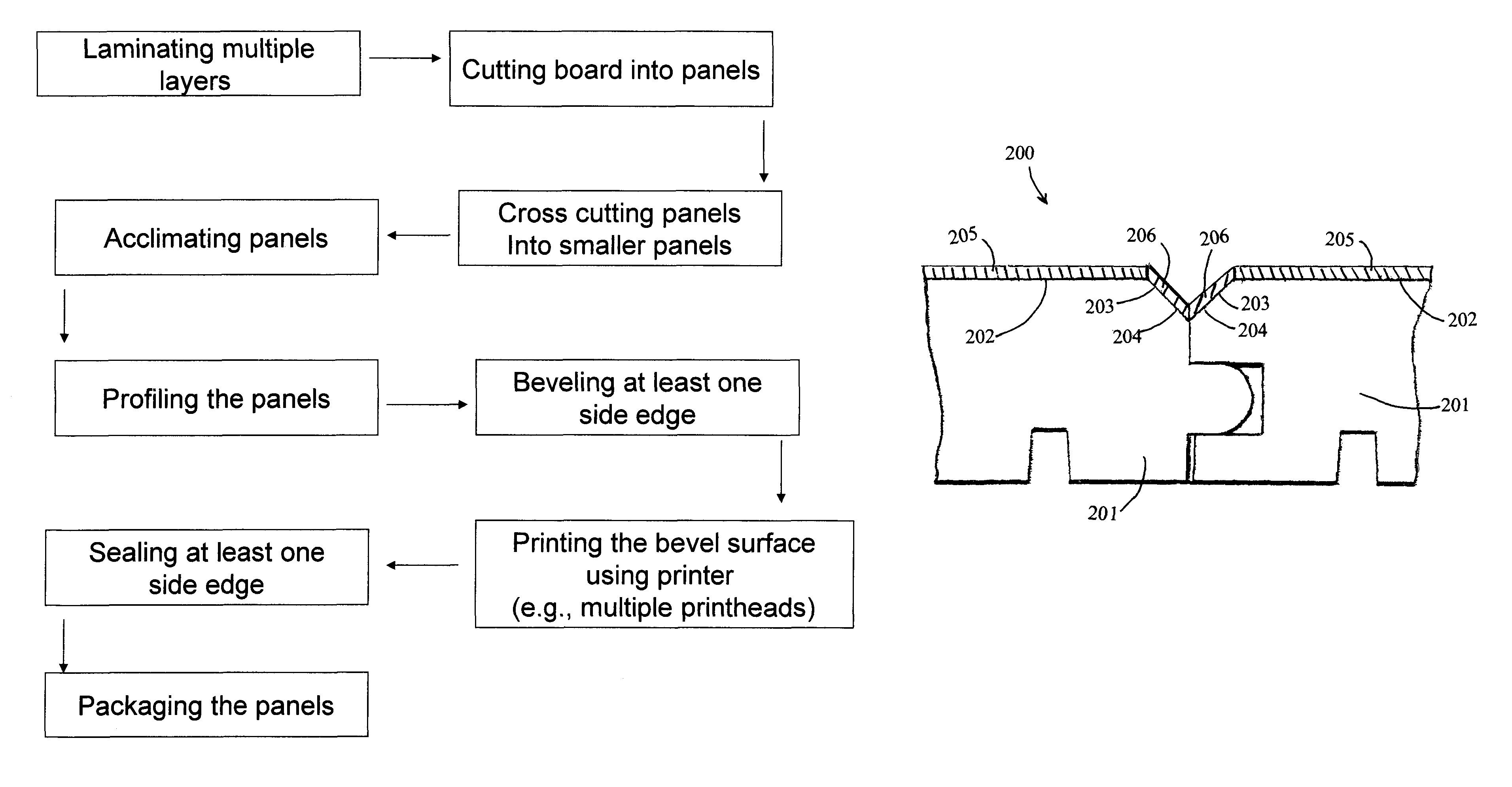
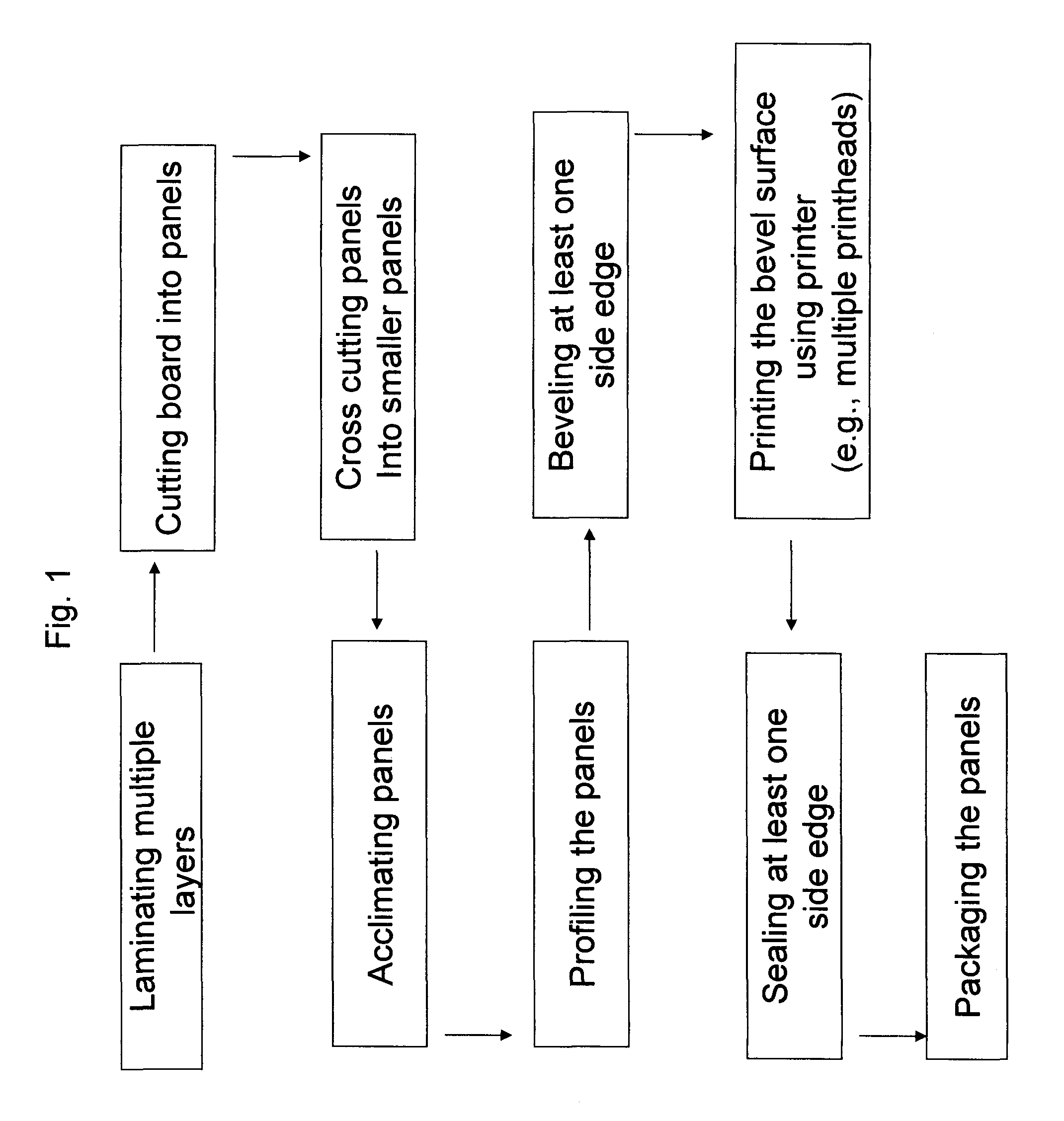
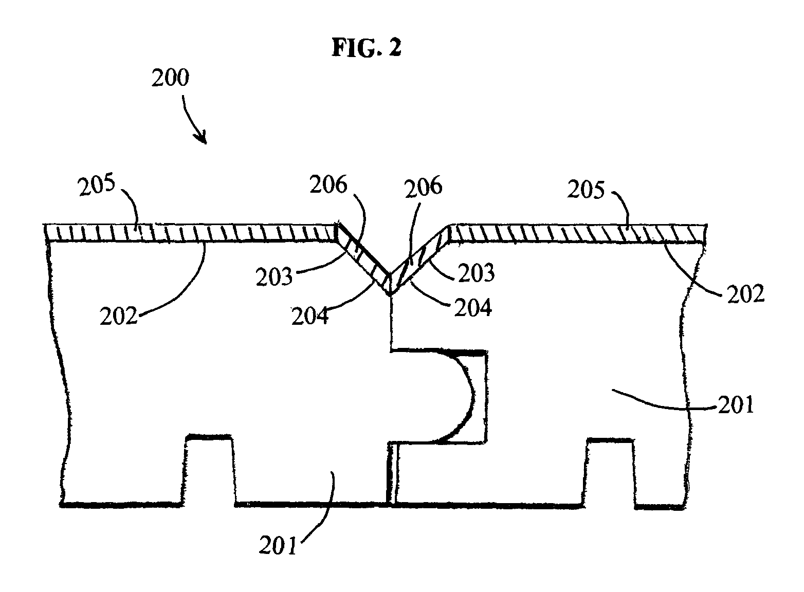
[0041]The present invention relates to methods and systems for decorating bevel surfaces (e.g., edges) and / or one or more other surfaces, such as surfaces of the tongue or groove present on laminated flooring. The present invention further relates to methods and systems of non-transfer printing, such as digital printing, on the bevel surfaces and / or one or more other surfaces, such as surfaces of the tongue and groove. According to various embodiments, the methods and systems can use ink jet (or laser printing) for printing on bevel surfaces and / or one or more other surfaces, such as surfaces of the tongue and / or groove that are present on laminated flooring, with colors and decorative patterns matching the décor patterns and face designs of laminated flooring.

[0042]The terms “face design,”“décor pattern,” and “print design” are used interchangeably herein when they relate to the top face or surface of the laminated flooring which comprises at least one design or pattern.

[0043]The t...


PUM

PropertyMeasurementUnit
angleaaaaaaaaaa
ink throw distanceaaaaaaaaaa
throw distanceaaaaaaaaaa

Abstract

Methods and systems for decorating at least one bevel surface or other surface of a laminated flooring are described. The bevel surface can be decorated by non-transfer printing such as digital printing. The digital printer can be an ink jet printer such as a piezoelectric drop-on-demand (DOD) printer that allows a color and pattern to be placed on the bevel surface that matches the print design (décor pattern or face design) of the laminated flooring. Other devices are provided such as a device that takes a picture of or scans an image of the print design, and modifies the taken picture or the scanned image so that the edge pattern thereof matches with an edge pattern of the print design.

Description

[0001]This application claims the benefit under 35 U.S.C. §119(e) of prior U.S. Provisional Patent Application No. 60 / 811,938, filed Jun. 8, 2006, which is incorporated in its entirety by reference herein.FIELD OF THE INVENTION[0002]The present invention in part relates to a product with a decorative surface having two different types of decorative materials adjacent to each other and that can be applied by different methods of applying the decoration, preferably wherein the decoration materials can not be visually discernable. One of the decorative materials can be a highly durable material that is used on the main surface of the flooring that withstands daily wear and tear from foot traffic and also resists gouging, abrasions, and scratches, and other damage from moving heavy objects. The other decorative material can be a less durable material that is applied, for instance, on recessed areas such as bevel edges, as well as the surfaces of tongue and groove joints that do not typi...

Claims


Application Information

Patent Timeline
Patent Type & Authority Patents(United States)
IPC IPC(8): E04C2/00E04B5/00
CPCB41J3/407B41M5/0041E04F15/02033E04C2/30B41J2/005B41M3/00Y10T428/24488Y10T428/24777Y10T428/24802
Inventor CHEN, HAO A.
Owner FLOORING IND LTD
Why Eureka
Try Eureka