Centrifugal bernoulli heat pump

a technology of heat pump and centrifugal force, which is applied in the field of centrifugal bernoulli heat pump, can solve the problems of radially outward movement of gas, cannot withstand centrifugal force,

Inactive Publication Date: 2011-04-05
MACHFLOW ENERGY INC
View PDF38 Cites 1 Cited by
  • Summary
  • Abstract
  • Description
  • Claims
  • Application Information

AI Technical Summary

Benefits of technology

[0009]The present invention uses pairs of rotating disks to create a Bernoulli heat pump. A heat pump transfers heat from a relatively cool heat source to a relatively warm heat sink. In the present invention, both the heat-source flow is either a gas or liquid; the heat-sink flow is a gas. The heat transfer takes place through an intermediary, one or more pairs of rotating disks that are good thermal conductors. The disks are in good thermal contact with both flows. In the present invention, the fundamental heat-pump action, that is, the transfer of heat from the cooler source to the warmer sink, occurs because rotation of the disk pairs creates a nozzled flow in which the local temperature in a region of the sink flow is below that of the source. The disks are in good thermal contact with both the source flow and the cold region of the sink flow, thereby enabling the flow of heat from the source to the sink. Local cooling of the heat-sink gas flow is caused by the Bernoulli effect.
[0012]If the separation between two corotating disks decreases with increasing radius, the two disks form a nozzle through which the gas is pulled by centrifugal force. The Bernoulli effect lowers the temperature of the flowing gas in the neck of this nozzle. The present invention exploits this temperature lowering by allowing heat flow through the disk and into the nozzled gas flow, where the temperature of the gas flow allows forced convection to occur.
[0015]According to another aspect of the invention, the surface of the disks can be engineered to restrict heat transfer to regions of the disk-gas interface where the transfer is most efficient.

Problems solved by technology

Unlike the solid material of the disk, however, the gas cannot withstand the centrifugal force, and moves radially outward.

Method used


Image

  • Centrifugal bernoulli heat pump
  • Centrifugal bernoulli heat pump
  • Centrifugal bernoulli heat pump

Examples


Embodiment Construction

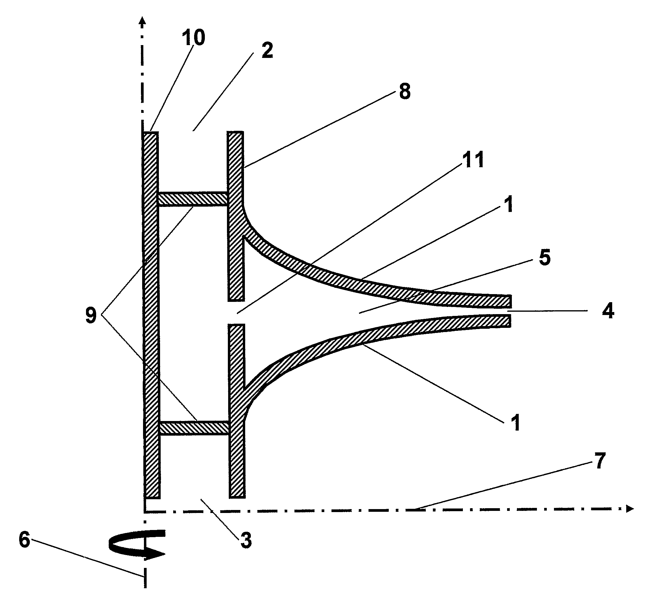
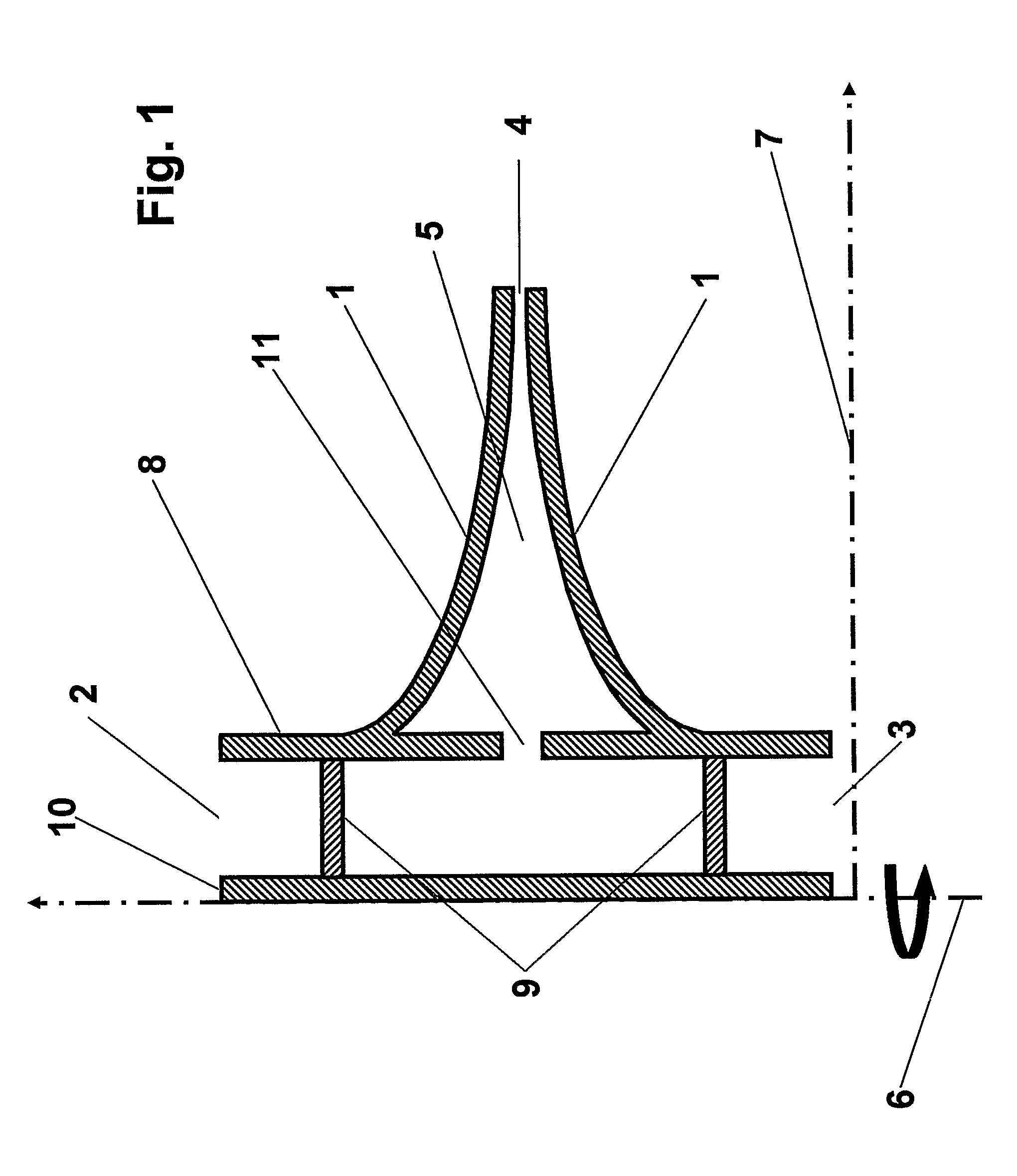
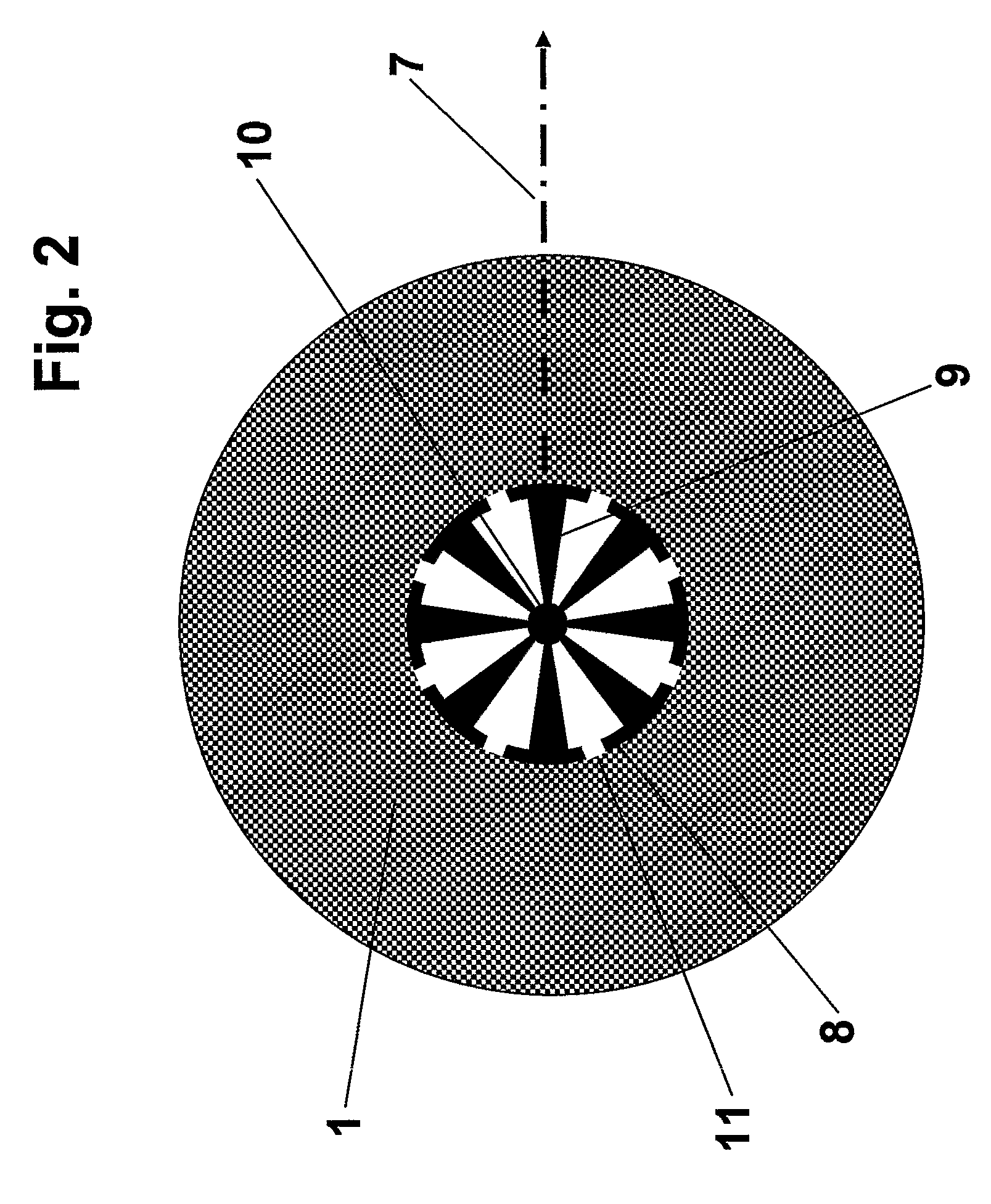
[0046]In embodiments of the invention, such as that shown in FIG. 1, one or more coaxial, thermally conducting, corotating disk pairs 1 are mounted on a common hub 8 to create a heat pump. The disks comprising the disk pairs are not planar; they are shaped such that the distance between their opposing surfaces decreases with increasing distance from their common rotation axis. The corotating disk pair 1 acts as a centrifugal pump drawing the gas through the nozzle 5 formed by the converging surfaces of the corotating disk pair 1. Embodiments of the present invention require a motor which causes the hub-disk assembly to rotate about its rotation axis. The motor can be one of many possible types, including electric, internal combustion, wind-powered, etc.

[0047]The corotating disk pair acts as a centrifuge because of the so-called no-slip boundary condition obeyed by the gas at the gas-disk interface. That is, the gas in the immediate vicinity of a disk surface moves circularly with th...


PUM


Abstract

Heat pumps move heat from a source to a higher temperature heat sink. This invention enables spontaneous source-to-sink heat transfer. Spontaneous heat transfer is accomplished by conducting heat from the source through rotating disks to a portion of the generally warmer sink flow that is cooled to a temperature below that of the source by the Bernoulli effect. The nozzled flow required for Bernoulli cooling is provided by the corotating disk pairs. The distance between the opposing surfaces of the disk pair decreases with distance from the rotation axis, forming a nozzle. The heat-sink flow through the nozzle is maintained by centrifugal force caused by the circular motion of the gas near the disk surfaces. Embodiments of the invention differ in the paths followed by the source and sink fluid flows, by the number of disk pairs and by the state (gas or liquid.) of the heat source.

Description

BACKGROUND OF THE INVENTION[0001]1. Field of the Invention[0002]The present invention relates to heat pumps, devices that move heat from a heat source to a warmer heat sink. More specifically, it relates to Bernoulli heat pumps.[0003]2. Discussion of Related Art[0004]Heat engines are devices that move heat from a source to a sink. Heat engines can be divided into two fundamental classes distinguished by the direction in which heat moves. Heat spontaneously flows “downhill”, that is, toward lower temperatures. As with the flow of water, such “downhill” heat flow can be harnessed to produce mechanical work, as illustrated by internal-combustion engines, e.g. Devices that move heat “uphill”, that is, toward higher temperatures, are called heat pumps. Heat pumps necessarily consume power. Refrigerators and air conditioners are examples of heat pumps. Common heat pumps employ a working fluid that transports heat by convection from the source to the sink. The temperature of the working fl...

Claims


Application Information

Patent Timeline
Patent Type & Authority Patents(United States)
IPC IPC(8): F25B9/00
CPCF04D29/281F25B23/00F25B9/002
Inventor WILLIAMS, ARTHUR R.AGOSTA, CHARLES
Owner MACHFLOW ENERGY INC
Why Eureka
Try Eureka