D/A converter circuit and digital input class-D amplifier

a converter circuit and digital input technology, applied in the field of digital to analog converter circuits, can solve problems such as limiting cycle components, and achieve the effect of high precision

Inactive Publication Date: 2011-04-05
YAMAHA CORP
View PDF5 Cites 17 Cited by
  • Summary
  • Abstract
  • Description
  • Claims
  • Application Information

AI Technical Summary

Benefits of technology

[0006]The present invention has been conceived in view of the above-described circumstance, and aims at providing a D / A converter circuit which enables D / A conversion with a high precision and can prevent occurrence of a limit cycle component in the case where an input signal is low, and can also prevent the effect of the dither signal from occurring in the analog signal which is the D / A conversion result.
[0008]According to the present invention, the respective analog signals corresponding to the plurality of lines of time-series digital signals and the analog signal corresponding to the reversal dither signal are added at the analog adder. In this case, a component corresponding to the component of the dither signal is included in the analog signal to which the respective analog signals corresponding to the plurality of lines of time-series digital signals are added, however, this component and the analog signal corresponding to the reversal dither signal are cancelled each other in accordance with the addition performed by the analog adder. Therefore, it is possible to prevent the component of the dither signal from appearing in the analog signal which is a D / A conversion result.

Problems solved by technology

Although the high linearity is obtained by the D / A converter circuit using the DEM decoder, the problem is that a limit cycle component appears in the analog signal which is the D / A conversion result, when the input digital signal has a somewhat different level from 0.
When the analog signal outputted from D / A converter circuit is used to drive a speaker, such a limit cycle component is not desirable because it becomes unpleasant noise to ears and is soundproofed from the speaker.
However, the above-mentioned direct current dither method has a disadvantage from the point that it needs a mean for preventing a DC offset from being supplied to the speaker which is a load, since the DC offset corresponding to the DC dither to be added to the digital signal which is to be processed by the DEM decoder appears in the analog signal which is the D / A conversion result.
Because the frequency of the component of the dither signal is low, there was a problem that it appears as a drive waveform of a load by passing an amplifier and the like, in the rear end of the D / A converter circuit.

Method used


Image

  • D/A converter circuit and digital input class-D amplifier
  • D/A converter circuit and digital input class-D amplifier
  • D/A converter circuit and digital input class-D amplifier

Examples


first embodiment

The First Embodiment

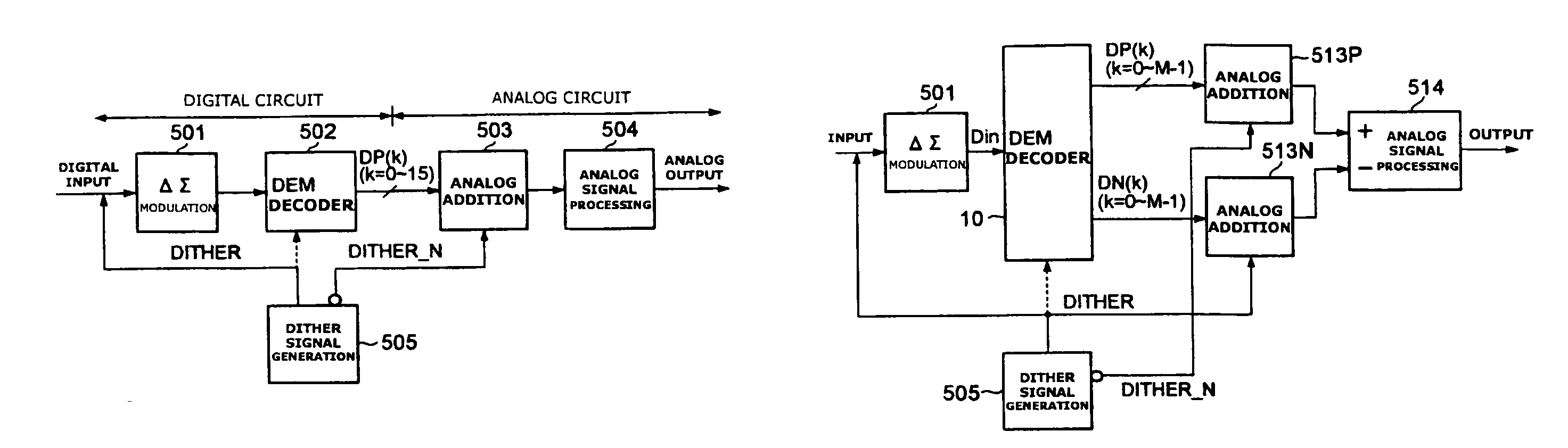
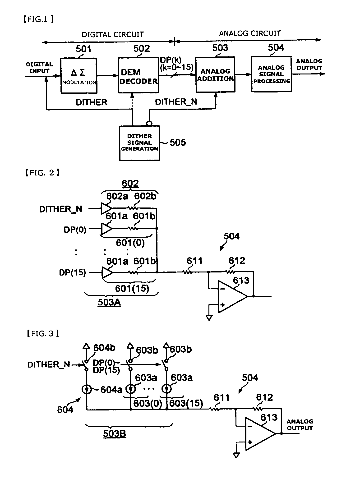
[0025]FIG. 1 is a block diagram showing the configuration of an audio circuit including D / A converter circuit which is the first embodiment of the present invention. The audio circuit has a ΔΣ modulation section 501, a DEM decoder 502, an analog addition section 503, an analog signal processing section 504 and a dither signal generation section 505. In this case, the DEM decoder 502, the analog addition section 503, and the dither signal generation section 505 are the main components of the D / A converter circuit according to the present embodiment.

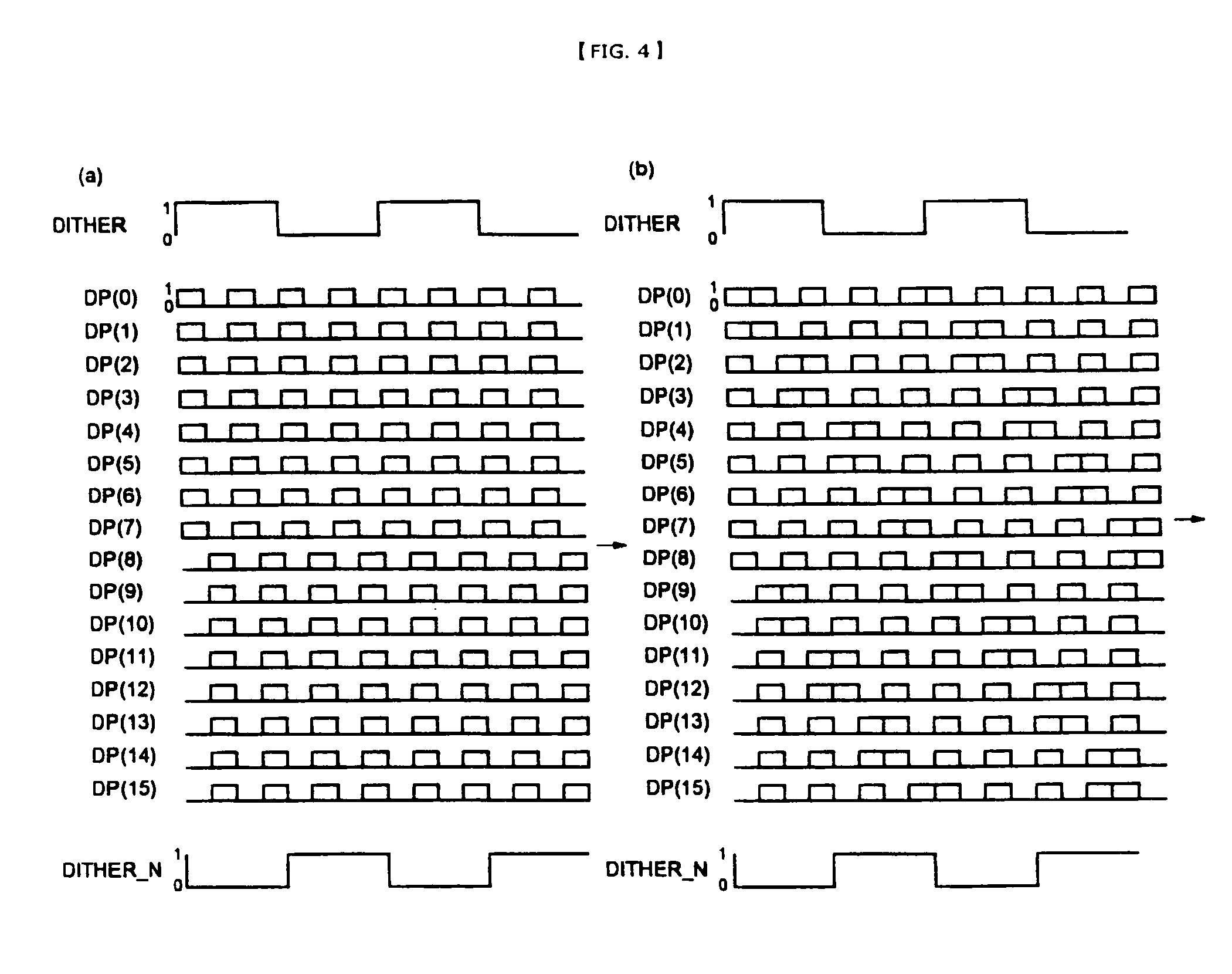
[0026]The ΔΣ modulation section 501 outputs a digital signal where the quantization noise of the input digital audio signal moves to high area side, by performing ΔΣ modulation to an input digital audio signal such as PCM signal and the like. The DEM decoder 502 is a circuit outputting a plurality of lines (in the example, 16 lines) of time-series digital signals DP(k) (k=0 to 15) which has a density of “1” or “0” confo...

second embodiment

The Second Embodiment

[0039]FIG. 5 is the block diagram showing the configuration example of an audio circuit including D / A converter circuit that is the second embodiment of the present invention. The audio circuit has a ΔΣ modulation section 501 similar to that of the first embodiment, a DEM decoder 10, analog addition sections 513P and 513N, an analog signal processing section 514 of differential input type and a dither signal generation section 505 similar to that of the first embodiment. In this case, the DEM decoder 10, the analog addition sections 513P and 513N, and the dither signal generation section 505 are the main components of the D / A converter circuit according to the present embodiment.

[0040]In FIG. 5, the DEM decoder 10 processes an input digital signal including the component of the dither signal, and outputs positive phase time-series digital signals DP(k) (k=0 to M−1) and negative-phase time-series digital signals DN(k) (k=0 to M−1) in equilibrium with the time-ser...

third embodiment

The Third Embodiment

[0046]FIG. 7 is a circuit diagram showing the configuration of a digital input class-D amplifier including D / A converter circuit which is the third embodiment of the present invention. In the present embodiment and the fourth to eighth embodiments described later, the D / A converter circuit according the second embodiment is applied to the digital input class-D amplifier. Also, although the digital input class-D amplifier according to the third to fourth embodiments includes circuits corresponding to the ΔΣ modulation section 501 and the dither signal generation section 505 of the second embodiment, they are not shown in the drawing.

[0047]In FIG. 7, voltage-current conversion sections 21(k) (k=0 to M−1) and a voltage-current conversion section 701 correspond to the analog addition section 513P of the second embodiment. The time-series digital signals DP(k) (k=0 to M−1) of positive-phase outputted from the DEM decoder 10 are supplied respectively to the voltage-cur...


PUM


Abstract

The present invention provides a D / A converter circuit which enables D / A conversion with a high precision and can prevent occurrence of a limit cycle component in the case where an input signal is low, and can also prevent the effect of dither signal from occurring in an analog signal which is a D / A conversion result.A dither signal generation section 505 outputs a dither signal (DITHER) which is an alternating current signal and a reversal dither signal (DITHER_N) inverted from the dither signal. A DEM decoder 502 processes an input digital signal including a component of the dither signal (DITHER), and outputs a plurality of lines of time-series digital signals having a density of “1” or “0” conforming to the input digital signal to be processed. An analog addition section 503 converts a plurality of lines of time-series digital signals and the reversal dither signal (DITHER_N) into an analog signal respectively and adds them, and outputs an analog signal which is a D / A conversion result.

Description

BACKGROUND OF THE INVENTION[0001]The present invention relates to a Digital-to-Analog converter circuit (hereinafter, simply referred to as D / A converter circuit) and a digital input class-D amplifier suitable for audio equipment, and the like.[0002]As a technique for enhancing the accuracy of D / A conversion, there is a DEM (Dynamic Element Matching) technique. In a D / A converter circuit using the DEM technique, a plurality of lines of time-series digital signals having a density of “1” or “0” is generated by a decoder called a DEM decoder conforming to an input digital signal, and an analog signal which is a D / A conversion result is created by converting the plurality of lines of time-series digital signals into an analog signal respectively and adding them. Although the high linearity is obtained by the D / A converter circuit using the DEM decoder, the problem is that a limit cycle component appears in the analog signal which is the D / A conversion result, when the input digital sig...

Claims


Application Information

Patent Timeline
Patent Type & Authority Patents(United States)
IPC IPC(8): H03M1/20
CPCH03F3/2173H03M1/0639H03M1/0673H03M3/328H03M7/3026H03M3/50H03M3/506H03M1/822
Inventor KAWAI, HIROTAKATSUJI, NOBUAKIMORISHIMA, MORITOOTANI, YOHEI
Owner YAMAHA CORP
Why Eureka
Try Eureka