Plugging methods and apparatus for particulate filters

a technology of particulate filter and plugging method, which is applied in the direction of manufacturing tools, separation processes, other domestic articles, etc., can solve the problems of unplugged cells, high variability in overall plug length, and unplugged cells, so as to reduce plug length variability, eliminate overflow of plugging material, and minimize the effect of missing plugs

Active Publication Date: 2011-04-12
CORNING INC
View PDF21 Cites 27 Cited by
  • Summary
  • Abstract
  • Description
  • Claims
  • Application Information

AI Technical Summary

Benefits of technology

[0018]The present inventive methods and apparatus may utilize existing cement compositions and rheologies, and are compatible for use with lasercut polymer masks. Advantageously, the methods and apparatus of the invention reduce plug length variability, minimizes missing plugs, and eliminates overflow of the plugging material from the cell channels to which the plugging material is applied. The methods and apparatus described herein are also highly repeatable and accurate, easily applied, and reduce unintended deformations of the honeycomb structure, and are particularly well adapted for the proposed use.

Problems solved by technology

There are numerous disadvantages to this particular process, including the high variability in overall plug length, misalignment of the mask with respect to the filter body, thereby causing unplugged cells, and the creation of unplugged cells due to dry cement that “flakes-off” into fresh cement prior to application.
Reusable masks can be less effective at plugging the cells because they cannot adjust to variations between the honeycomb structures.
The equipment used in these conventional processes is also incompatible with laser-cut polymer masks as these laser-cut masks stay with the cemented body when the associated plugging machines open for part release (See U.S. Pat. No. 4,557,773).
Another problem with silicon masks (as shown in U.S. Pat. No. 4,427,728) is that they are sized so as to align with the outer edges of the filters, thereby allowing the cement to flow along and adhere to an outer edge of the filter.
This is a significant limitation with respect to the tape strips which must be individually applied across each end face, a time-consuming task.
The reusable matrix and gasket of the second embodiment may be more quickly applied and removed, but like the rigid plate embodiments, is less easily adapted to distortions in the cell locations of the end faces.
Moreover, increasing cellular densities render such an approach unworkable.
Additionally, variations in the surface of the plugging material on the plugging apparatus can be transferred into the substrate causing variations in the length of intrusion of the plugs.
The length of intrusion should be deep enough to secure a good blocking of the sealed channels, but is desirably limited because an increase in plug length results in the loss of porous wall surface area.

Method used


Image

  • Plugging methods and apparatus for particulate filters
  • Plugging methods and apparatus for particulate filters
  • Plugging methods and apparatus for particulate filters

Examples


Embodiment Construction

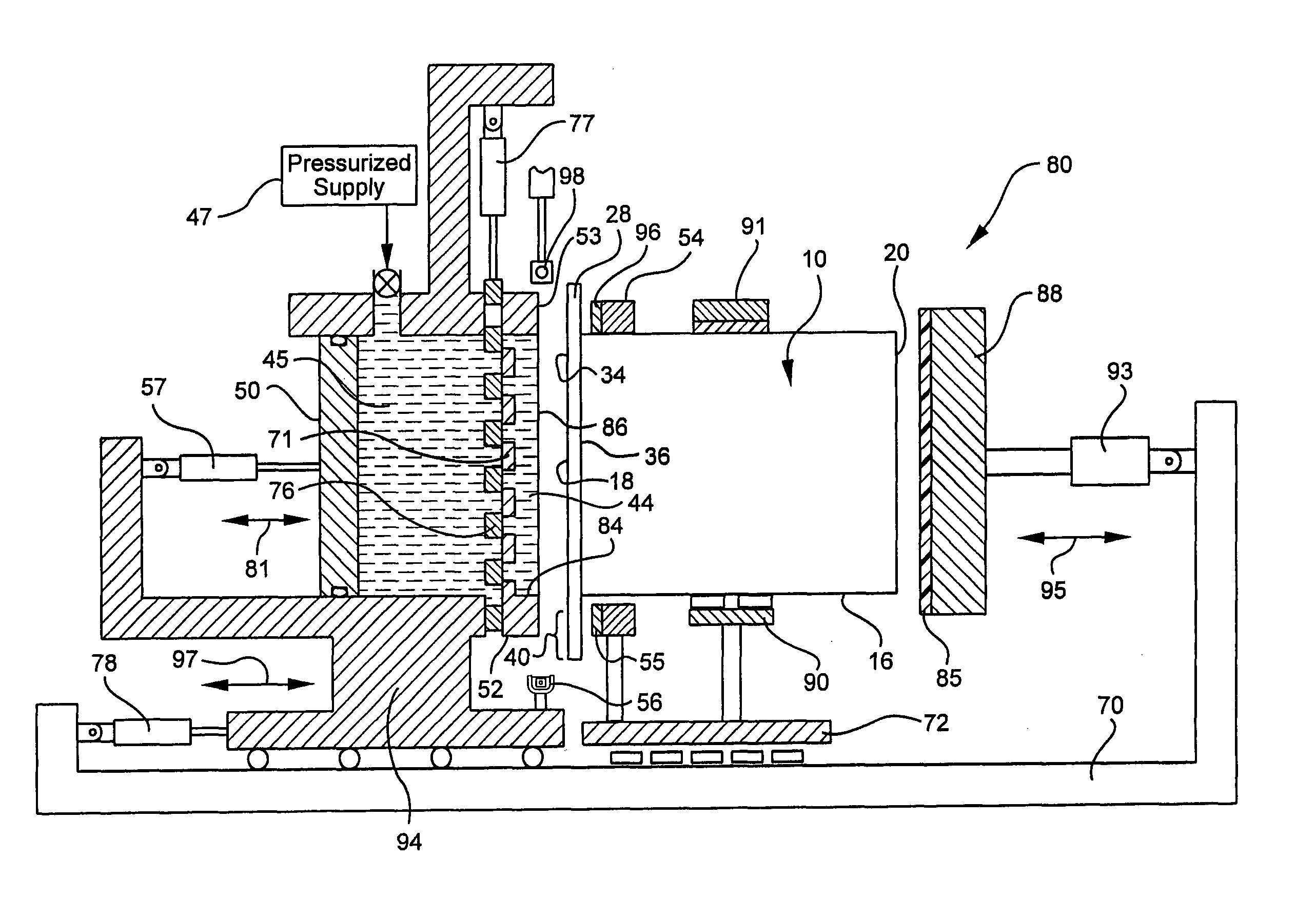
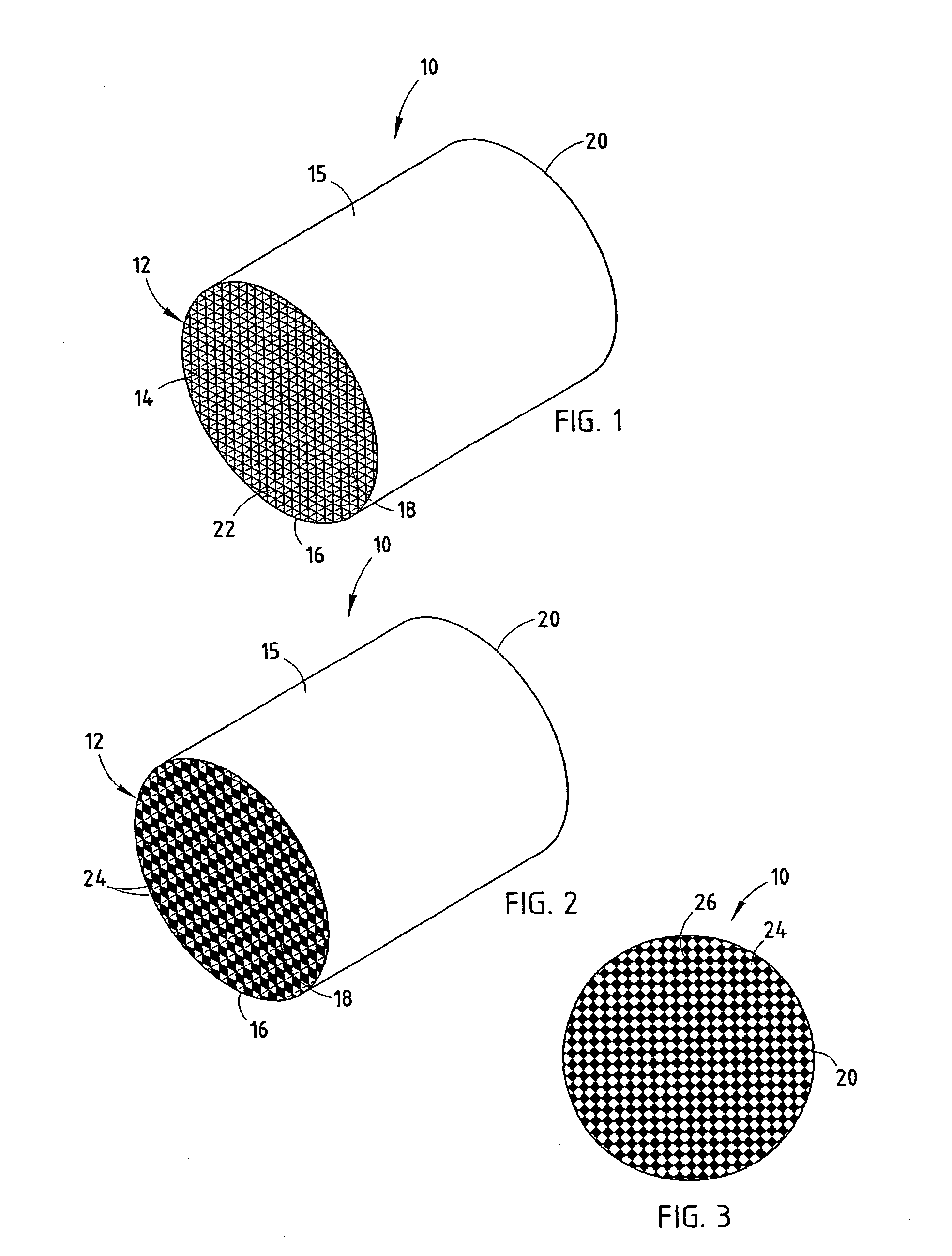
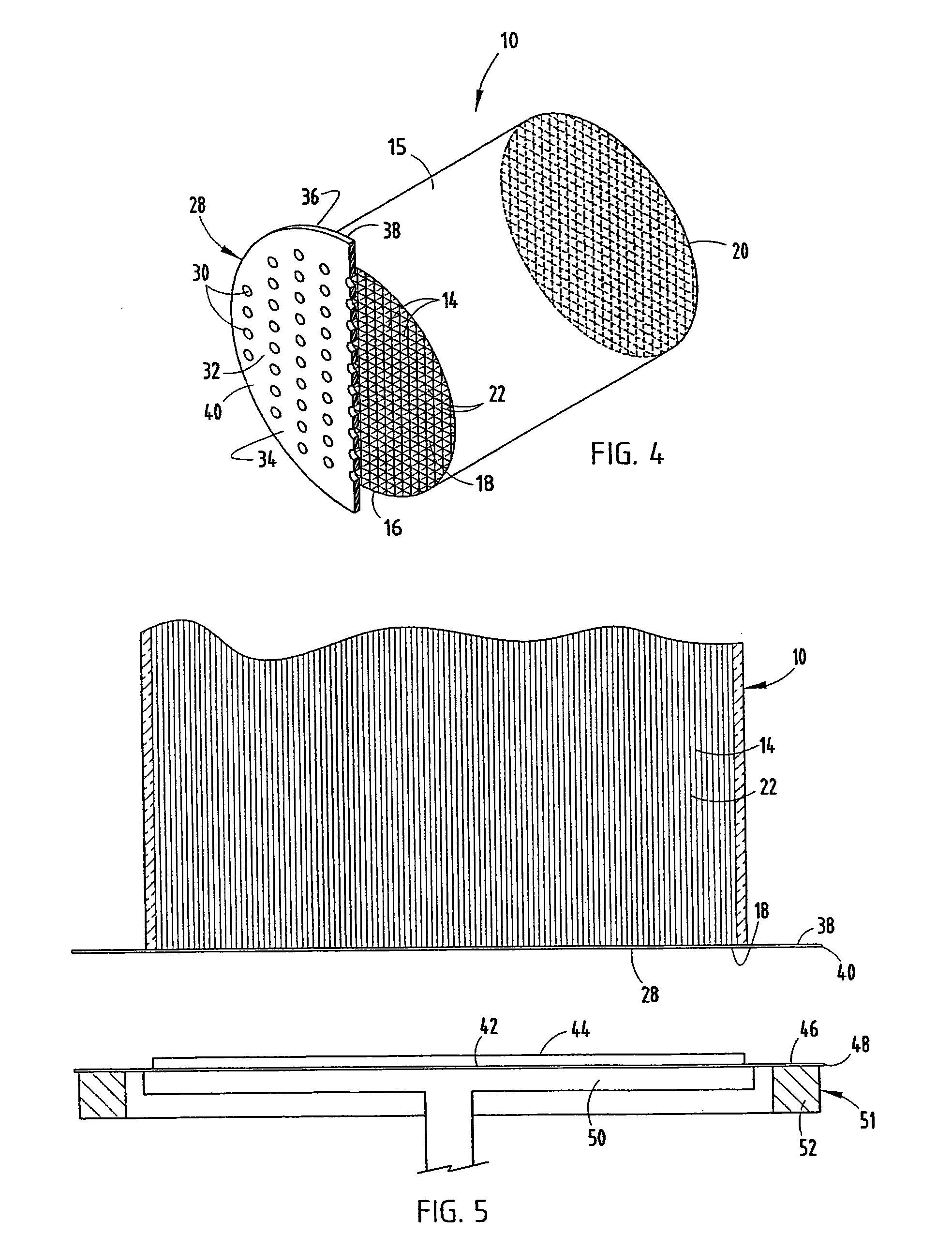
[0037]For purposes of description herein, the terms “upper,”“lower,”“right,”“left,”“rear,”“front,”“vertical,”“horizontal,” and derivatives thereof shall relate to the invention as oriented in FIGS. 1 and 4. However, it is to be understood that the invention may assume various alternative orientations and step sequences, except where expressly specified to the contrary. It is also to be understood that the specific devices and processes illustrated in the attached drawings, and described in the following specification are exemplary embodiments of the inventive concepts defined in the appended claims. Hence, specific dimensions and other physical characteristics relating to the embodiments disclosed herein are not to be considered as limiting, unless the claims expressly state otherwise.

[0038]Honeycomb structures for solid particulate filter bodies, such as the filter body 10, and other applications may be formed of a variety of materials including ceramics, glass-ceramics, glasses, m...


PUM

PropertyMeasurementUnit
distanceaaaaaaaaaa
pressureaaaaaaaaaa
pressureaaaaaaaaaa

Abstract

Methods and apparatus for plugging cells of honeycomb structures are disclosed. A first method covers the honeycomb structure's end face with a mask having a body and plurality of sized openings positioned to oppose certain cell channels, wherein the outer edge of the body extends radially outwardly from the end face. A film also extends outwardly of the end face, and a plug of material is provided upon the film. The mask and film material are sealed to one another, and a force is applied to the film forcing the material through the mask and into the cells. Also disclosed is adhering a mask to a first end face of the honeycomb structure such that the mask has an outer portion that extends radially beyond an outer edge of the honeycomb; providing a volume of plugging material; clamping the outer portion between a first clamping portion and a second clamping portion; and transferring the plugging material into the honeycomb. Also disclosed are methods and apparatus for cutting the plugging material between the mask and a pre-plugging chamber to form a substantially planar surface thereon.

Description

RELATED APPLICATIONS[0001]This application claims priority to, and the benefit of, U.S. Provisional Patent Application No. 60 / 638,275 entitled “Flat Patty Plugging of Particulate Filters” filed Dec. 21, 2004.FIELD OF THE INVENTION[0002]This invention relates to the charging of flowable materials into selected cells of a honeycomb structure, and, more particularly, to methods and apparatus for selectively manifolding, i.e., plugging, cells of a honeycomb structure for the fabrication of ceramic filter bodies and other selectively sealed honeycomb structures.BACKGROUND OF THE INVENTION[0003]Honeycomb structures having traverse cross-sectional cellular densities of approximately ten to one hundred cells or more per square centimeter have several uses, including solid particulate filter bodies and stationary heat exchangers. Wall flow particulate filter applications require selected cells of the structure to be sealed or plugged by manifolding and the like at one or both of the respecti...

Claims


Application Information

Patent Timeline
Patent Type & Authority Patents(United States)
IPC IPC(8): B29C45/14B29C48/305
CPCB01D46/0001B01D46/2418B28B11/007B29C70/766B28B11/006B01D46/2466Y10T428/24149Y10T428/24157B01D46/2482B01D46/2459
Inventor MUDD, JAMES RAYMONDPOWELL, ROBERT ALANRYSZYTIWSKYJ, WILLIAM PAULSCHOONMAKER, JASON EDWARDWEACHOCK, RICHARD HENRY
Owner CORNING INC
Why Eureka
Try Eureka