
Redundancy strategy selection scheme

a strategy selection and redundancy technology, applied in the field of redundancy strategy selection scheme, can solve the problems of inefficient transmission and introduce significant delays, and achieve the effect of increasing flexibility in selection and reducing the load of signaling

Active Publication Date: 2011-04-12
NOKIA TECH OY
View PDF16 Cites 10 Cited by
  • Summary
  • Abstract
  • Description
  • Claims
  • Application Information

AI Technical Summary

Benefits of technology

[0009]It is therefore an object of the present invention to provide an improved redundancy strategy selection scheme, by means of which a signaling load can be reduced while increasing flexibility in the selection.
[0021]Accordingly, a network operator is able to select the redundancy strategy to be used by the terminal devices simply by selecting a predetermined strategy information and signaling this information to the terminal device. Thereby, the terminal devices do not independently select their own strategies. The proposed selection scheme requires less signaling between the network and the terminal device, as only an information indicating the strategy or sequence can be transmitted from the network to the terminal device. Furthermore, if the Node B and the terminal device both know which transmission strategies or sequences are available, then signaling overhead can be further reduced by simply signaling an information indicating the strategy but not each parameter of the sequence.
[0023]The transmitting step may be performed by using a higher layer signaling. As an example, the higher layer signaling may be a Radio Resource Control signaling. The use of a higher layer signaling provides the advantage that the lower layer signaling is freed from this additional signaling which reduces transmission delay.
[0027]The transmission may be performed by broadcasting the strategy information to all terminal devices located within a predetermined area. Thereby, all terminal devices within the specific area are controlled to use the same redundancy strategy, so that a good adaptation to a specific capability of this network area can be assured.

Problems solved by technology

However, to provide the same quality as in a wired system, FEC overhead could lead to very inefficient transmissions.
This is disadvantageous in that a retransmission will require relatively large buffers and will introduce significant delays.
This may, however, cause problems in cases where different Node Bs have different capabilities which the UE should take into account.
Another problem in the uplink direction is that signaling from the UE to the Node B will introduce overhead from all UEs operating in the enhanced DCH mode.

Method used


Image

  • Redundancy strategy selection scheme
  • Redundancy strategy selection scheme

Examples


first embodiment

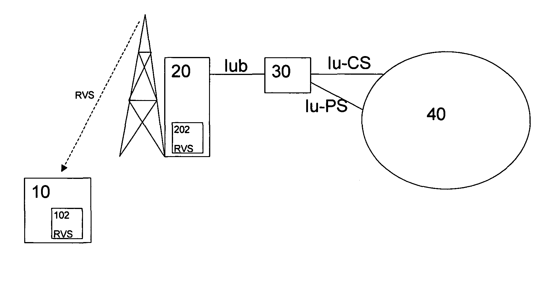
[0048] the RV strategies can be numbered, e.g., CC could have strategy number “0”, PIR could have the strategy number “1”, and FIR could have the strategy number “2”. Of course, also other strategies could be specified and correspondingly numbered. At the beginning of a connection, the RNC 30 may signal to the UE 10 the RV strategy to be used for the connection, using RRC signaling. Thus, if there are for example four different strategies specified, two bits are needed to signal the strategy using a binary information pattern.

[0049]The RV parameters used in the uplink direction can then be signaled outband by the UE 10, i.e., using an own signaling channel protected separately from the data. By specifying the individual RV strategies, the number of bits required for transmitting the RV parameters and thus the number of uplink outband information can be made dependent on the selected RV strategy. For instance, if the CC strategy is selected, no signaling is required for the RV parame...

second embodiment

[0050] the sequence or RV parameters to be used by the UE 10 is signaled to the UE 10 from the RNC 30 at the beginning or at set-up of the connection by using RRC signaling. The network may select a predetermined sequence to be used for this connection, e.g., a sequence of {0,1,2,4}. This second preferred embodiment provides the advantage that the network or network operator can define any sequence of RV parameters suitable for a specific application or network environment. However, in this case more bits have to be signaled. In the above example of eight different RV parameter combinations, three bits are required for each RV combination. Thus, if four RV combinations are specified for the sequence, then twelve bits are needed in total to specify the sequence.

third embodiment

[0051] the RV sequences can be specified in the network specification so as to be pre-configurable at the Node B 20 and the UE 10. The selected RV strategy can than be cell- or network-specific and can be broadcast on a common channel. The RV strategy is then the same for all UEs in the specific cell or network. If the reason for the use of a certain RV strategy is the Node B capability, for example, and therefore all UEs in the concerned cell should use the same RV strategy, then signaling capacity can be saved if the RV strategy is broadcast to all UEs at the same time.

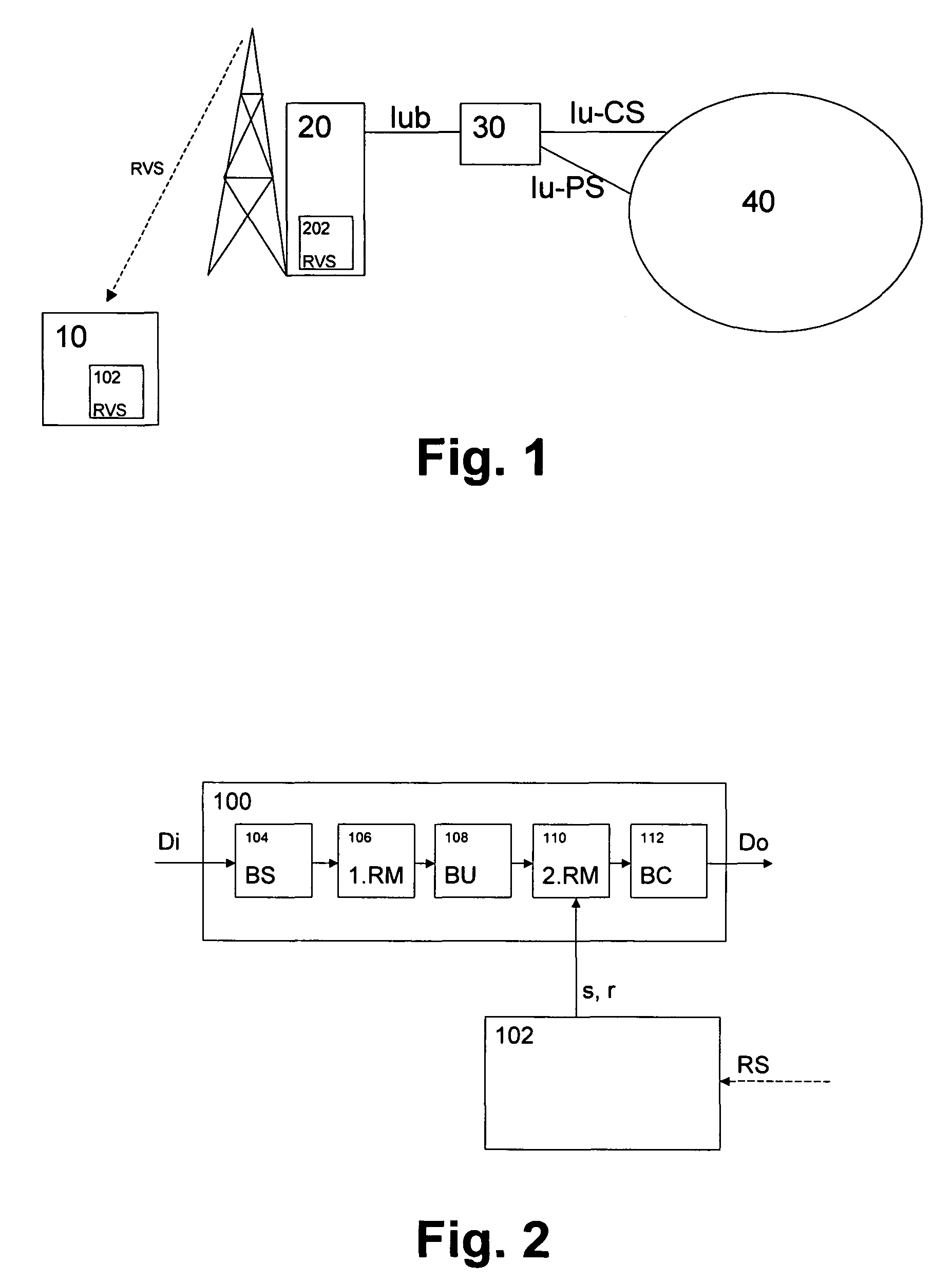
[0052]FIG. 2 shows a schematic block diagram of a repeat request functionality 100 provided at the UE 10 with an adaptable or controllable RV parameter generating unit 102 which can be controlled based on the strategy information RS received from the network.

[0053]The repeat request functionality 100 can be used for the enhanced uplink DCH (E-DCH) channel or any other physical or transport channel and is configured ...


PUM


Abstract

The present invention relates to method, terminal device and network device for providing redundancy parameters for an automatic repeat request processing at a terminal device. At least one sequence of redundancy parameters is selected from a predetermined set of sequences and is signaled to the terminal device by using a strategy information indicating the selected parameter sequence. Thereby, the network operator is able to select the redundancy version strategy to be used by the terminal device, while little signaling is required between the network and the UE. Moreover, a flexible strategy can be provided where individual redundancy version strategies can be allocated to the connections.

Description

BACKGROUND OF THE INVENTION[0001]1. Field of the Invention[0002]The present invention relates to a method, terminal device, and network device for providing redundancy parameters for an automatic repeat request processing at a terminal device of a communication network, particularly for uplink transmissions in a third generation mobile communication network.[0003]2. Description of the Related Art[0004]For wired links, reliability in data communications is traditionally obtained thanks to repetition. A packet is retransmitted when the previous attempt was unsuccessful. Such mechanism is called Automatic Repeat Request (ARQ). In the case of wireless transmissions, due to the poor quality of the link, packets should be protected against channel noise, fading due to mobility, and interference created by other users. Protection is mainly given by forward error coding (FEC), e.g. transmitting additional bits incorporated into the data packet. However, to provide the same quality as in a w...

Claims


Application Information

Patent Timeline
Patent Type & Authority Patents(United States)
IPC IPC(8): G08C25/02H04L1/18H04L1/16H04W88/02H04W24/02
CPCH04L1/1819G08C25/02H04W24/02H04W88/02H04L1/16H04L1/18H04W28/02
Inventor MALKAMAKI, ESAFREDERIKSEN, FRANK
Owner NOKIA TECH OY
Learn More