Adjusting device for a pneumatic disc brake

a technology of disc brake and adjusting device, which is applied in the direction of axially engaging brakes, slack adjusters, brake actuating mechanisms, etc., can solve the problems of no longer being able to rotate the threaded tube, no disk, and approximately 40 mm wear travel, etc., to achieve low processing costs, low cost, and robust

Inactive Publication Date: 2011-04-19
KNORR-BREMSE SYST FUER NUTZFAHRZEUGE GMBH
View PDF16 Cites 31 Cited by
  • Summary
  • Abstract
  • Description
  • Claims
  • Application Information

AI Technical Summary

Benefits of technology

[0018]Against this background, it is the object of the invention to develop the generic adjusting device in such a way that it can be manufactured with as few components as possible and inexpensively with a low processing expenditure. In addition, optimization of the function and service life is preferably also aimed for.
[0019]A basic principle of the adjusting device is again a combination of the freewheel and the overload coupling in one functional unit which is configured here, however, to be particularly inexpensive, robust and functionally reliable, in particular by means of a conical seat as an inexpensive failsafe functional element.

Problems solved by technology

Disk brakes of this type require a mechanical transmission means in order to generate the required brake application of force, as the force of the pneumatically loaded brake cylinders is limited on account of the pressure level (currently approximately 10 bar) and the limited overall size of the brake cylinders.
As two linings are installed, the result is therefore a wear travel of approximately 40 mm, without taking the disk wear into consideration.
However, this is only the case when the air play is too great.
If the air play has the correct size, the brake linings come into contact with the brake disk at the same time as the switching fingers come into contact with the switching fork of the adjusting device, and a rotation of the threaded tube is no longer possible on account of the high frictional force which is caused by this in the thread.

Method used


Image

  • Adjusting device for a pneumatic disc brake
  • Adjusting device for a pneumatic disc brake

Examples


Embodiment Construction

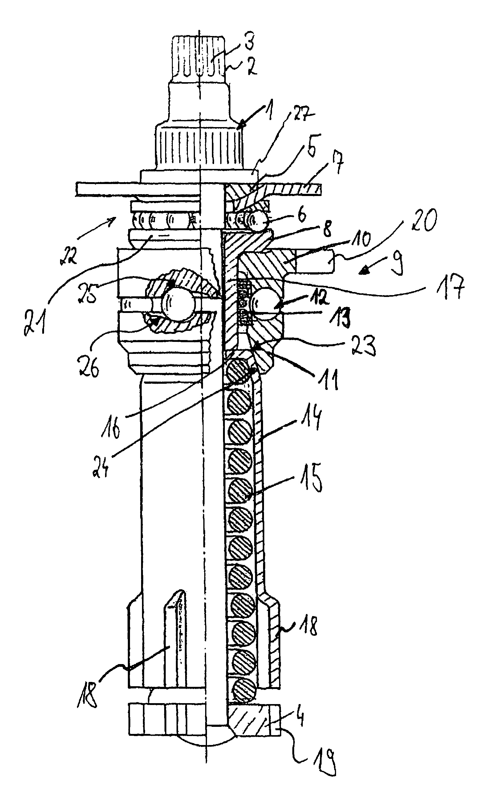
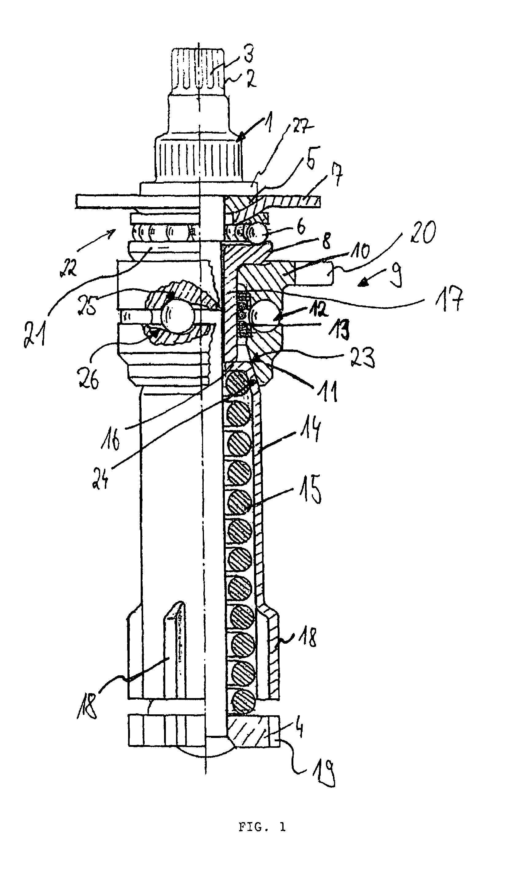
[0022]FIG. 1 shows an adjusting device which, like the adjusting devices of German patent document DE 197 29 024 C1, can be introduced into a surrounding hollow rotary spindle, relative to which it can be displaced axially but cannot be rotated.

[0023]The adjusting device has a central spindle 1 which serves as an axle and extends over the entire length of the adjusting device. Said spindle 1 ends, in its region which protrudes outward out of the rotary spindle and the brake caliper, in a drive journal 2 having a profiling 3, which drive journal 2 allows the spindle 1 to be rotated back during a lining change, in order to reset the rotary spindle for a lining change by the amount of wear of the brake linings.

[0024]A star-shaped driver 4 is arranged at the opposite end of the spindle 1, which star-shaped driver 4 is designed for engaging into an axially extending internal profiling (at least one groove) of the surrounding rotary spindle (not shown here), with the result that, during r...


PUM


Abstract

An adjusting device for adjusting the wear of the friction surface on the brake lining and brake disc of a pneumatic disc brake having a clamping device that is actuated by a rotary lever is provided. The device preferably can be inserted into a rotary spindle of the disc brake. An anti-friction body is positioned on both axial sides of a drive element, with the one bodies being a ramp coupling with a freewheeling function. The ramp coupling has coupling bushes and clamping balls, and the coupling bush on the driven side being supported on a spring sleeve. A conical seat is configured between the coupling bush and the sprung sleeve cooperates with the ramp coupling to preclude locking of the coupling bushes.

Description

[0001]This application is a Continuation of PCT / EP2005 / 008403, filed Aug. 3, 2005, and claims the priority of DE 10 2004 037 771.5, filed Aug. 4, 2004, the disclosures of which are expressly incorporated by reference herein.BACKGROUND AND SUMMARY OF THE INVENTION[0002]The invention relates to an adjusting device for a pneumatically actuated disk brake.[0003]A first adjusting device is known from German patent publication DE 40 34 165, reference being made to the full contents of this document. In particular, the adjusting device of the invention is likewise suitable for a disk brake which is actuated by compressed air, in particular in a sliding caliper design, as is shown in this document. Moreover, they can also be used, however, in fixed caliper or pivoting caliper disk brakes which are actuated by compressed air.[0004]Pneumatically actuated disk brakes of this type now belong to the standard equipment of heavy commercial vehicles, where they replace the previously customary drum...

Claims


Application Information

Patent Timeline
Patent Type & Authority Patents(United States)
IPC IPC(8): F16D55/08
CPCF16D65/567
Inventor IRASCHKO, JOHANN
Owner KNORR-BREMSE SYST FUER NUTZFAHRZEUGE GMBH
Why Eureka
Try Eureka