

Constant voltage boost power supply
a power supply and constant voltage technology, applied in the direction of dc-dc conversion, power conversion systems, oscillation generators, etc., can solve the problem that the charge pump in which the conventional clock frequency control is performed cannot be used as the internal boost power supply
- Summary
- Abstract
- Description
- Claims
- Application Information
AI Technical Summary
Benefits of technology
Problems solved by technology
Method used
Image

Examples
first embodiment
On-Off Control Constant Voltage Boost Power Supply
[0030]First, a constant voltage boost power supply that realizes a stable boost operation by on-off control will be described.
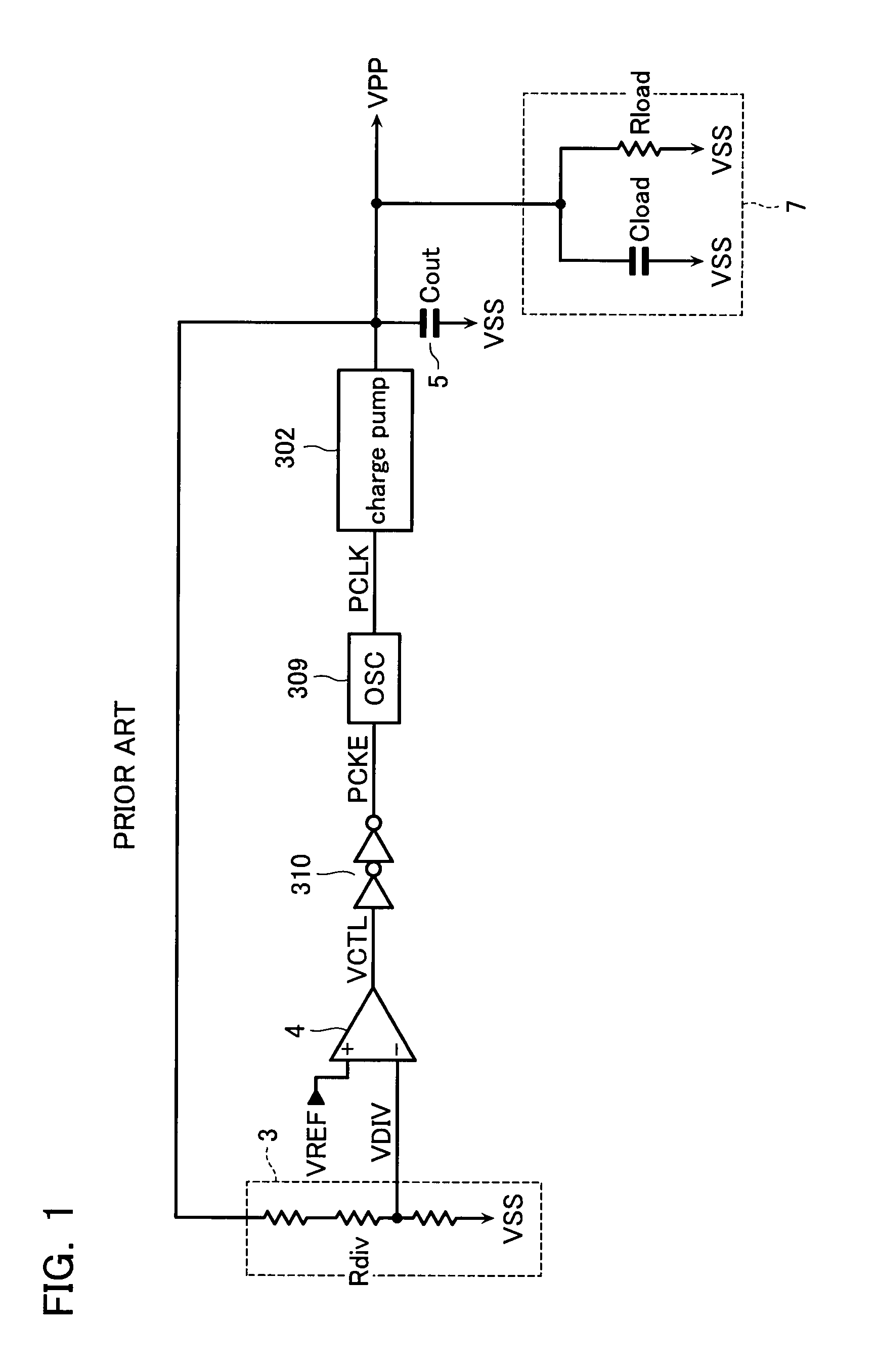
[0031]FIG. 1 is a block diagram illustrating an on-off control constant voltage boost power supply.
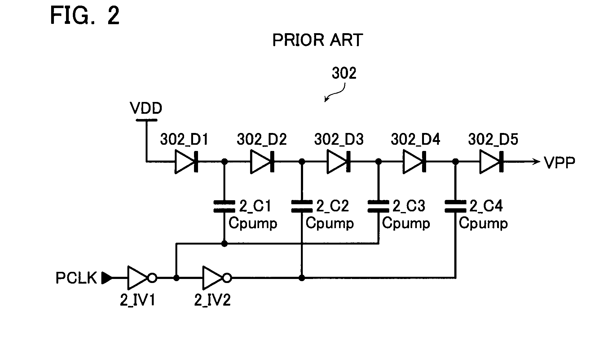
[0032]The on-off control constant voltage boost power supply includes an on-off control oscillator (OSC) 309 and a charge pump 302. The oscillator 309 steadily oscillates a clock signal PCLK when an oscillation enable signal PCKE is activated. The charge pump 302 receives the clock signal PCLK, and performs a pumping operation in synchronization with the clock signal PCLK. The on-off control constant voltage boost power supply also includes a voltage dividing circuit 3 and a differential amplifier 4. The voltage dividing circuit 3 divides an output voltage VPP of the charge pump 302 with a resistance. In the differential amplifier 4, an inverting input “−” and a noninverting input “+” receive a monitor voltage VD...
second embodiment
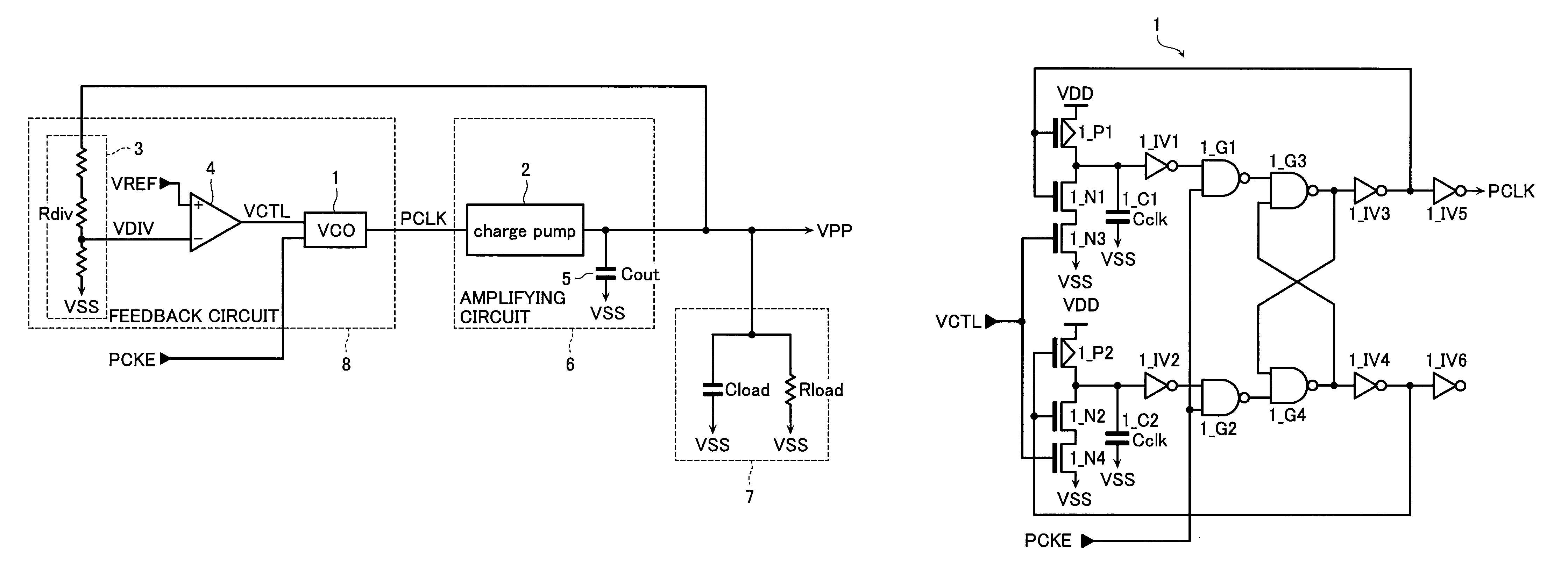
[0100]FIG. 11 is a block diagram illustrating a constant voltage boost power supply according to a second embodiment of the invention.
[0101]In the constant voltage boost power supply of the second embodiment, the stability of the output voltage VPP is further improved compared with the first embodiment.
[0102]An entire configuration of the constant voltage boost power supply of the second embodiment is substantially similar to that of the first embodiment. Points different from those of the first embodiment will mainly be described below.
[0103]The configuration of the constant voltage boost power supply of the second embodiment differs from that of the first embodiment in that the monitor voltage VDIV of the voltage dividing circuit 3 is fed into a noninverting terminal “+” of a differential amplifier 104 described later while the reference voltage VREF is fed into an inverting input “−”. Therefore, the control voltage / VCTL (the sign “ / ” indicates a superior line in FIG. 11) that is...
third embodiment
[0126]FIG. 14 is a block diagram illustrating a constant voltage boost power supply according to a third embodiment of the invention.
[0127]The constant voltage boost power supply of the third embodiment has the configuration simpler than that of the second embodiment and the stability of the output voltage VPP, which is higher than that of the first embodiment.
[0128]The configuration of the constant voltage boost power supply of the third embodiment differs from that of the second embodiment in that the voltage supplied to the differential amplifier becomes the output voltage VPP. Therefore, in the third embodiment, an open-loop differential amplifier 204 is used instead of the differential amplifier 104 of the second embodiment.
[0129]Advantageously the closed-loop differential amplifier 104 of the second embodiment is hardly influenced by the variation of the production process because the gain of the closed-loop differential amplifier 104 can be adjusted by a resistance ratio of t...
PUM
 Abstract
Description
Claims
Application Information