Current drive-type apparatus and display apparatus

a drive-type device and display device technology, applied in the direction of instruments, television systems, discharge tubes luminescnet screens, etc., can solve the problem of difficulty in achieving the above-described frame size reduction conventional method, and achieve the effect of small wiring and small circuit area

Active Publication Date: 2011-04-19
CANON KK
View PDF15 Cites 1 Cited by
  • Summary
  • Abstract
  • Description
  • Claims
  • Application Information

AI Technical Summary

Benefits of technology

[0017]According to the current drive-type apparatus of the present invention, in the area in which the column control circuit is disposed, it is possible to realize a small wiring and a small circuit area.

Problems solved by technology

Incidentally, the display apparatus using the organic EL device suffers from the occurrence of an area (dark spot) in which light is not emitted due to permeation or entrance of moisture or oxygen into the organic EL device or a deterioration in luminance.
The display panel may preferably be lightweight and compact, so that a reduction in size of the frame portion is required, but it is difficult to achieve the frame size reduction in the above described conventional method.

Method used


Image

  • Current drive-type apparatus and display apparatus
  • Current drive-type apparatus and display apparatus
  • Current drive-type apparatus and display apparatus

Examples


first embodiment

[0028]FIG. 1 shows a schematic layout of a display apparatus according to a First Embodiment of the present invention.

[0029]The display apparatus shown in FIG. 1 includes a display area 6 in which pixels (constituents) each comprising an EL device such as an organic EL device or the like and a pixel circuit (device control circuit) including a thin film transistor (TFT) are arranged in a matrix. The display apparatus further includes a contact hole 2 for connecting a transparent electrode connected to an output of the EL device with a common voltage line (common interconnecting line), an external terminal 5 through which an image signal, a control signal, and power are externally supplied, and an adhesion area 4 for effecting adhesion of a sealing plate (substrate).

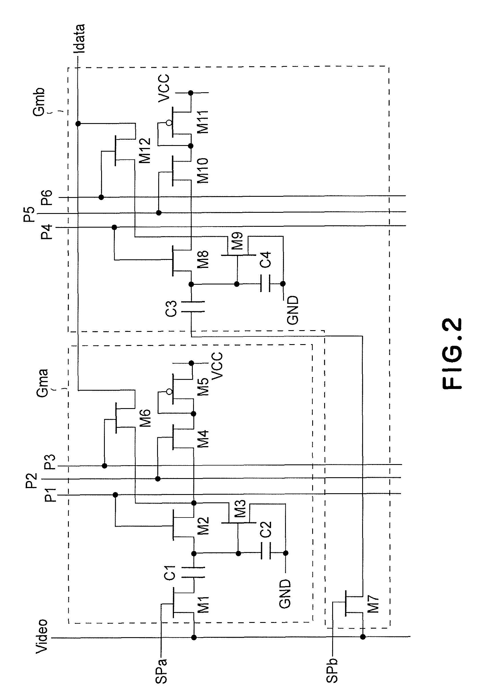
[0030]In this embodiment, a column control circuit 37 for outputting a data signal to the pixel circuit is divided into two column control circuits which are disposed so that the contact hole 2 is sandwiched therebetween....

second embodiment

[0050]The above described display apparatus of the First Embodiment is capable of constituting an information display apparatus which is an apparatus capable of realizing a mobile phone, a mobile computer, a still camera, a video camera, and a multifunction apparatus of these apparatuses. The information display apparatus includes an information input portion. For example, in the case of the mobile phone, the information input portion is constituted by containing an antenna. In the case of a PDA or the mobile computer, the input portion includes an interface portion for a network. In the case of the still camera or the video (movie) camera, the information input portion includes a sensor portion such as CCD or CMOS.

[0051]As a suitable embodiment, a digital camera using the display apparatus described in the First Embodiment is used in electronic equipment will be described.

[0052]FIG. 6 is a block diagram of an example thereof of a digital still camera. Referring to FIG. 6, an entire...


PUM


Abstract

A display apparatus includes a display area, in which pixels each including an EL device and a pixel circuit are arranged in a matrix on a substrate, and a column control circuit for controlling the pixel circuit column by column. The EL device is disposed between a lower pixel electrode and an upper transparent electrode on the substrate. The pixel electrode is electrically connected to the pixel circuit, and the transparent electrode is electrically connected to a common interconnecting line via a contact hole. The contact hole and the common interconnecting line are disposed to surround a periphery of the display area. The column control circuit is divided into two circuits one of which is disposed between the contact hole and the display area and the other of which is disposed outside the area between the contact hole and the display area.

Description

FIELD OF THE INVENTION AND RELATED ART[0001]The present invention relates to a current drive-type device, a display apparatus, and a camera which have an area in which a plurality of constituents, each including a current drive-type device and a device control circuit for controlling current passing through the current drive-type device, is disposed on a substrate. The present invention is suitably used in a display apparatus using an electroluminescence (EL) device which produces luminescence by injecting current therein.[0002]In recent years, display apparatuses using EL devices have attracted attention as display apparatuses in place of a CRT or an LCD. Of these EL devices, application and development of an organic EL device, which is a light-emitting device of a current control-type, in which luminance is controlled by current flowing in the device, have been actively effected. In organic EL display including a peripheral circuit, a thin film transistor (TFT) is used in not only...

Claims


Application Information

Patent Timeline
Patent Type & Authority Patents(United States)
IPC IPC(8): H04N5/222H01J63/04G09G3/30H01L27/14
CPCG09G3/3233G09G3/3283H01L27/3276G09G2300/0842G09G2300/0861G09G2300/0408H10K59/131
Inventor NAKAMURA, KOHICHIKAWASAKI, SOMEI
Owner CANON KK
Why Eureka
Try Eureka