Solderable elastic electric contact terminal

a technology of electric contact terminal and elastic material, which is applied in the direction of non-printed jumper connection addition, coupling device connection, dielectric characteristics, etc., can solve the problems of not being able to provide excellent elasticity in a predetermined height or less, electric contact terminal formed of only metal sheets, etc., and achieve good elasticity and good electrical conductivity

Active Publication Date: 2011-04-26
JOINSET
View PDF15 Cites 26 Cited by
  • Summary
  • Abstract
  • Description
  • Claims
  • Application Information

AI Technical Summary

Benefits of technology

[0007]An object of the present invention is to provide an elastic electric contact terminal having good elasticity and good electrical conductivity.

Problems solved by technology

However, the electric contact terminals formed of only the metal sheet, because of metal characteristics or structures, cannot provide excellent elasticity in a predetermined height or less.
To increase the elasticity, the metal sheet must be bent in a predetermined shape to have a bent height that mainly determines the height of the electric contact terminal, so that the electric contact terminal cannot provide elasticity in a predetermined height or less.
In addition, since a single press mold can form products having an identical shape, additional expensive press molds are needed to form products having different shapes.
Furthermore, the light-weight electric contact terminal formed of a metal sheet can be moved by the wind supplied in a surface mounting process, thereby causing defect.
According to this patent, an additional adhesive is needed to fix an electrically conductive gasket material and a solderable support layer, thereby causing inconvenience.
According to this patent, a compression hole is provided to an electrically conductive gasket material, and an electrically conductive support layer, that goes through a crimp process, is provided to a bottom surface of the electrically conductive gasket material, thereby reducing the productivity of electromagnetic interference (EMI) gasket assemblies.
That is, after the electrically conductive gasket material is manufactured, the electrically conductive support layer, that is separately manufactured, is inserted into the compression hole of the electrically conductive gasket material and then pressed, thereby causing inconvenience.
Hence, a size of the electrically conductive support layer in the compression hole is limited thereby, so that an adhesive force is not sufficient between the electrically conductive gasket material and the electrically conductive support layer.

Method used


Image

  • Solderable elastic electric contact terminal
  • Solderable elastic electric contact terminal
  • Solderable elastic electric contact terminal

Examples


Embodiment Construction

[0031]Now, preferred embodiments of the present invention will be described in detail with reference to the accompanying drawings.

1. One Embodiment

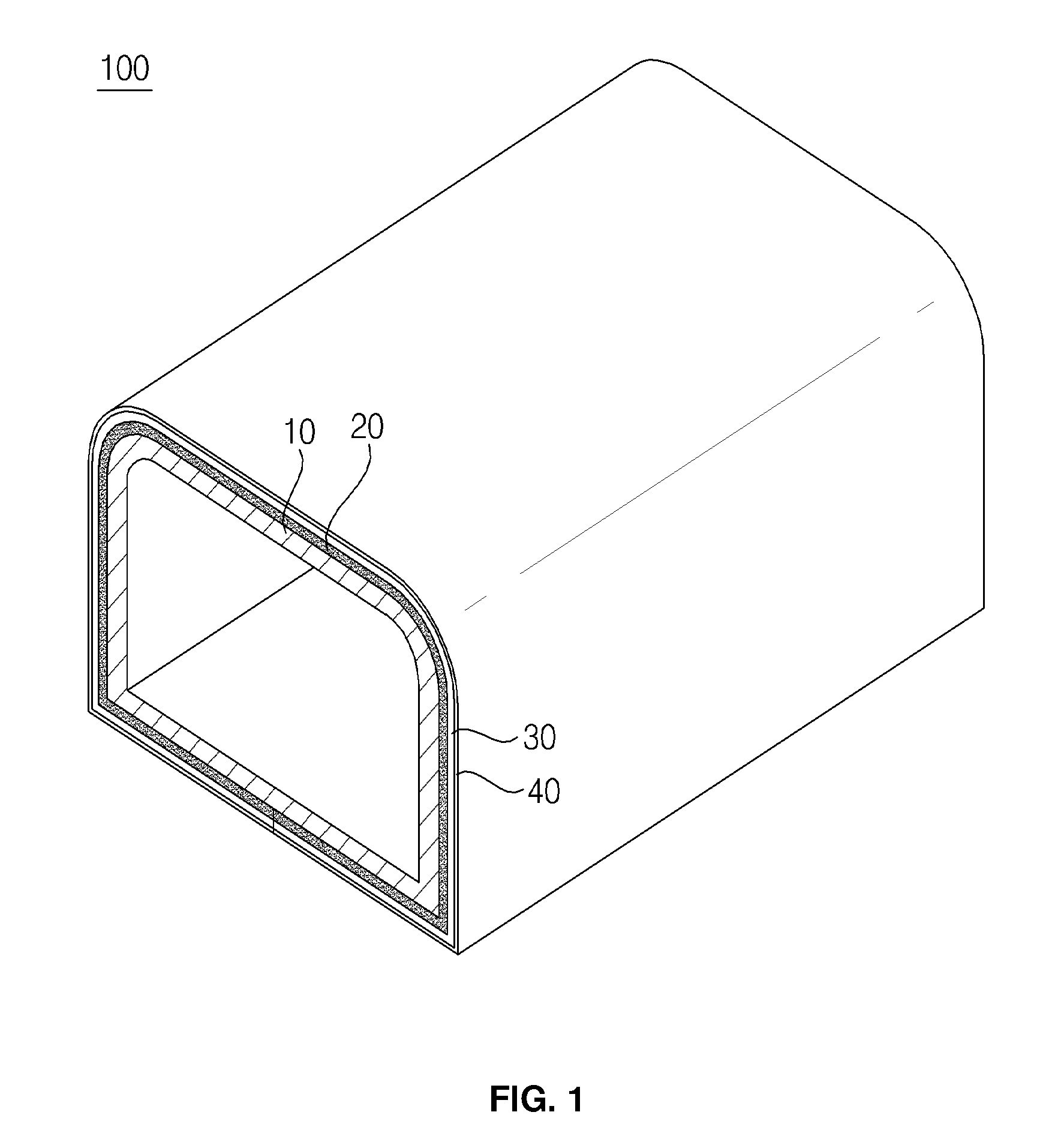
[0032]FIG. 1 is a view of an electric contact terminal 100 according to one embodiment of the present invention.

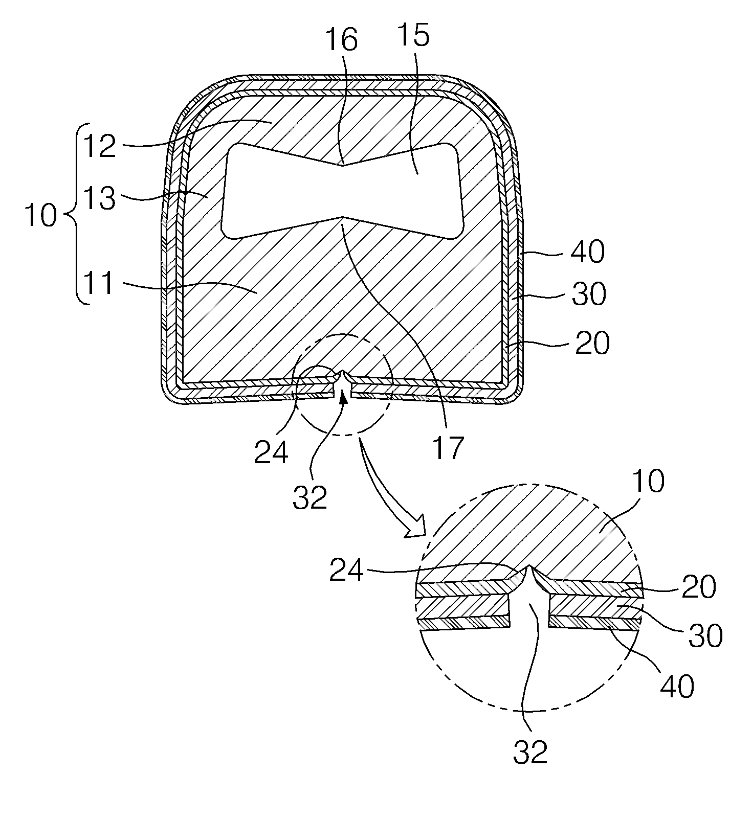
[0033]Referring to FIG. 1, the elastic electric contact terminal 100 includes a tube-shaped insulating elastic core 10, an insulating non-foam rubber coating layer 20, and a heat-resistant polymer film 30 having a metal layer 40 provided to a surface thereof, which are sequentially stacked.

[0034]In this structure, the tube-shaped elastic core manufactured through an extrusion process is applied, thereby reducing manufacturing costs, adjusting an elastic force and a pressing force to control the size of a through hole of the tube, and efficiently manufacturing a small product. Also, the insulating non-foam rubber coating layer maintains an adhesive force and an elastic force before and after a soldering process and during a repea...


PUM

PropertyMeasurementUnit
thicknessaaaaaaaaaa
thicknessaaaaaaaaaa
thicknessaaaaaaaaaa

Abstract

Provided is a solderable elastic electric contact terminal. The solderable elastic electric contact terminal includes a tube-shaped insulating elastic core, an insulating non-foam rubber coating layer adhered to the insulating elastic core to surround the insulating elastic core, and a heat-resistant polymer film having one surface adhered to the insulating non-foam rubber coating layer to surround the insulating non-foam rubber coating layer, and another surface integrally provided with a metal layer.

Description

FIELD OF THE INVENTION[0001]The present invention relates to an electric contact terminal, and particularly, to an elastic electric contact terminal adapted to perform a soldering process on the elastic electric contact terminal while electrically and mechanically connecting an object to a printed circuit board. More particularly, the present invention relates to an elastic electric contact terminal adapted to perform a reflow soldering process with a surface mounting process on the elastic electric contact terminal.BACKGROUND OF THE INVENTION[0002]Generally, solderable elastic electric contact terminals must have high electrical conductivity and excellent elastic resilience and must be resistant to a soldering temperature.[0003]Related art reflow-solderable electric contact terminals are formed mainly of metal. Specifically, beryllium copper is widely used for the electric contact terminals because it has excellent elastic resilience and high electrical conductivity. For example, a...

Claims


Application Information

Patent Timeline
Patent Type & Authority Patents(United States)
IPC IPC(8): H01R12/00
CPCH01R12/57H05K3/4015H01R13/24H05K3/222H05K3/325H01R12/714H05K2201/0133H05K2201/0154H05K2201/083H05K3/341
Inventor KIM, SUN-KICHOCHEON, HAN-JINYEO, HWAN-MIN
Owner JOINSET
Why Eureka
Try Eureka