Varistor and light emitting device

a light-emitting device and varistor technology, applied in the direction of resistor details, solid-state devices, semiconductor devices, etc., can solve the problems of affecting the operation of the varistor, the inability to efficiently conduct heat from the metal portion to the varistor, and the weak bonding strength between the two, so as to achieve the effect of sufficient bonding strength and efficient heat radiation

Inactive Publication Date: 2011-04-26
TDK CORPARATION
View PDF9 Cites 7 Cited by
  • Summary
  • Abstract
  • Description
  • Claims
  • Application Information

AI Technical Summary

Benefits of technology

[0005]Varistors can protect electronic elements, such as a semiconductor light emitting element and an FET (Field Effect Transistor), from ESD (Electrostatic Discharge) surges when connected in parallel to the electronic elements. The electronic elements include ones which generate heat during their operation. High temperature state of the electronic element causes deterioration in characteristics of the element itself, and thereby affecting its operation. Therefore it is necessary to radiate the generated heat efficiently.
[0006]The present invention has been accomplished in order to solve the above problem and an object of the invention is to provide a varistor and a light emitting device capable of efficiently radiating heat.

Problems solved by technology

High temperature state of the electronic element causes deterioration in characteristics of the element itself, and thereby affecting its operation.
However, when the metal is brought into contact with one surface of the outer side of the varistor element body, the bonding strength between them is weak, and thereby in some cases, the varistor element body and the metal are separated from each other.
In this case, heat conducted from the metal portion to the varistor cannot be radiated efficiently.

Method used


Image

  • Varistor and light emitting device
  • Varistor and light emitting device
  • Varistor and light emitting device

Examples


first embodiment

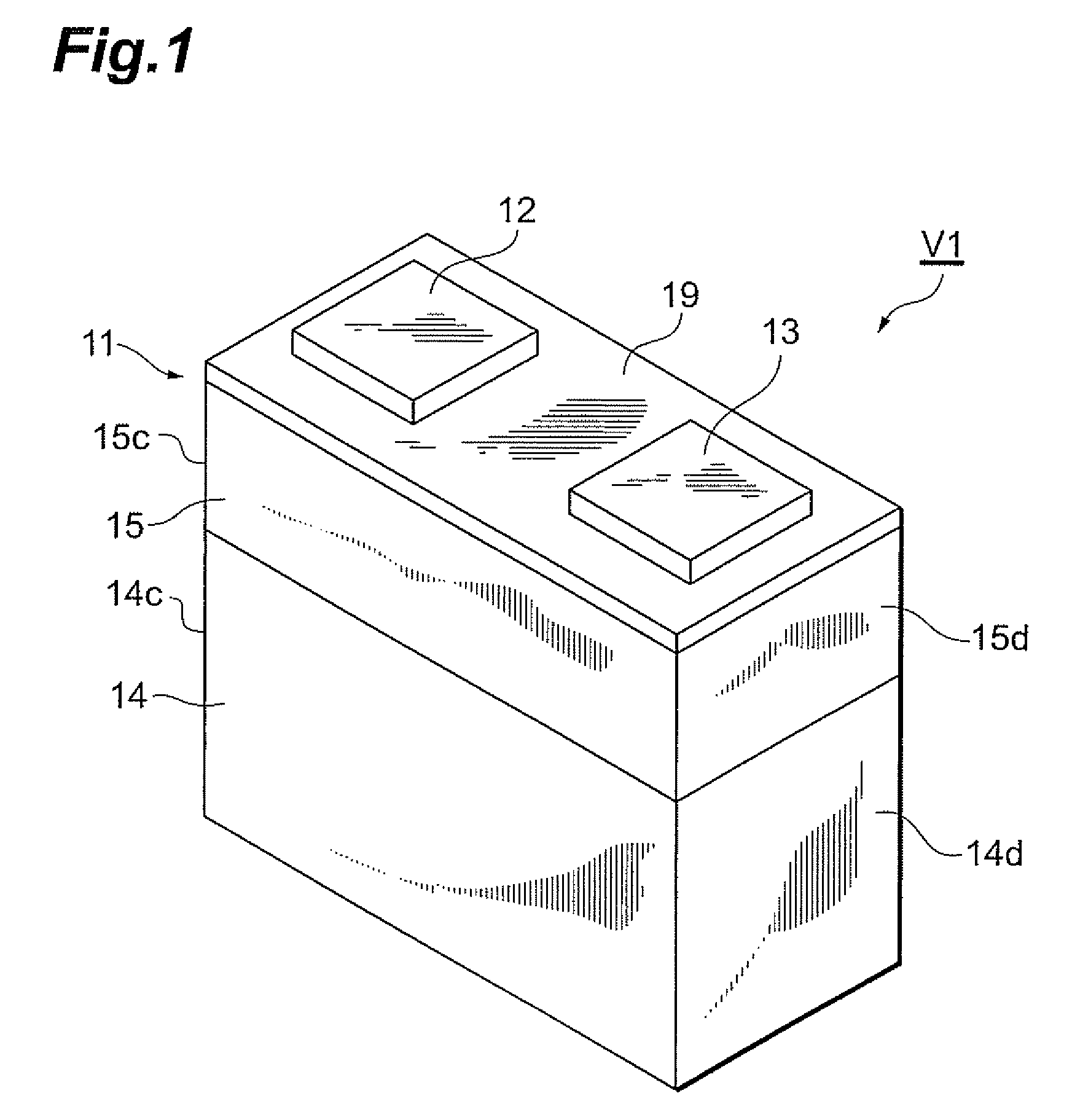
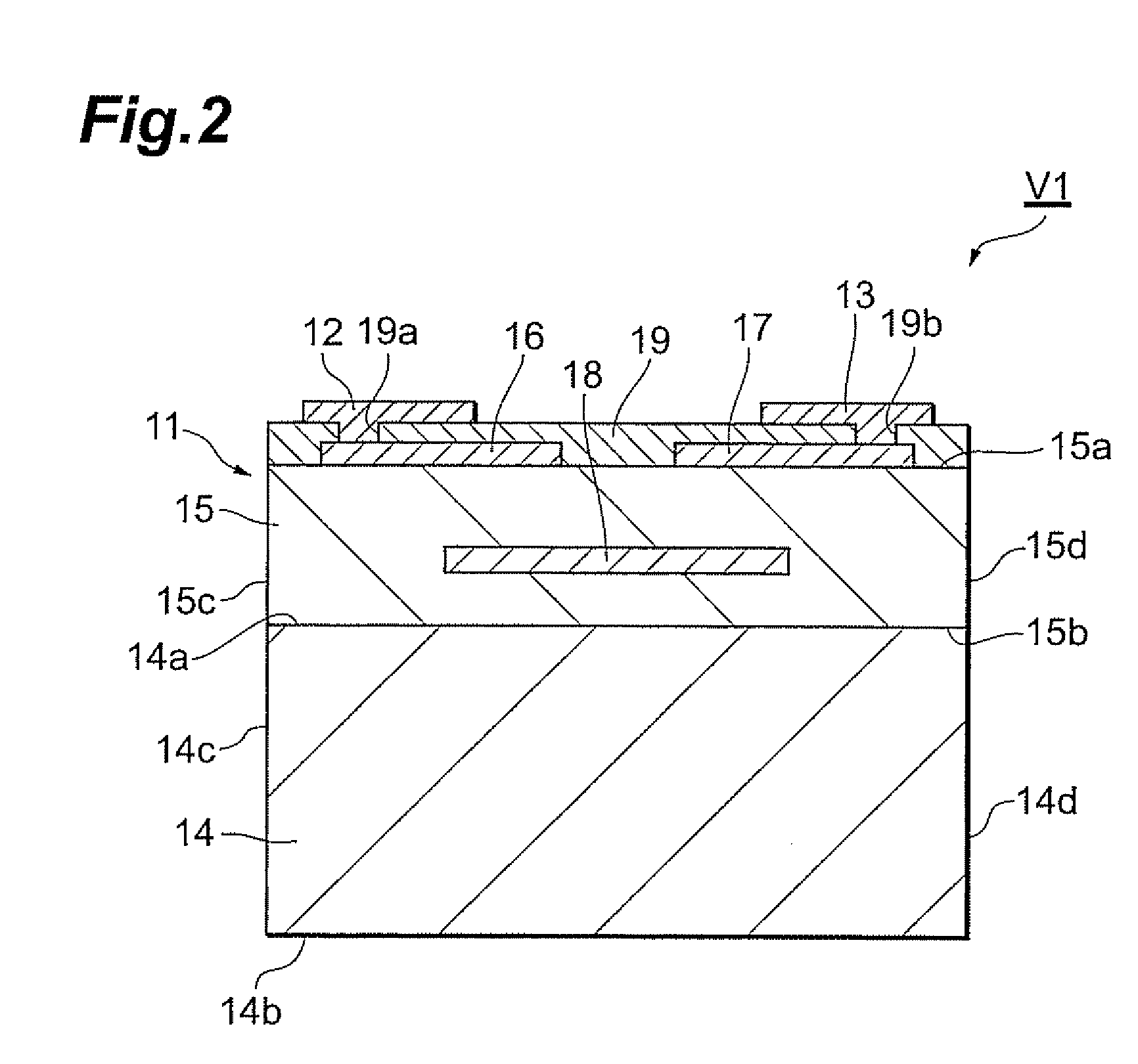
[0029]FIG. 1 is a schematic perspective view of a varistor in accordance with a first embodiment of the present invention. Moreover, FIG. 2 is the schematic cross-sectional view thereof. As illustrated in FIGS. 1 and 2, a varistor V1 includes a varistor portion 11, a pair of external electrodes 12 and 13, and a heat radiating portion 14, and has a shape of substantially rectangular parallelepiped.

[0030]The varistor portion 11 includes a varistor element body 15, a first internal electrode 16, a second internal electrode 17, and a third internal electrode 18. The varistor element body 15 has a shape of substantially rectangular parallelepiped, and has surfaces 15a and 15b facing each other, surfaces 15c and 15d facing each other, which are perpendicular to the surfaces 15a and 15b, and two surfaces facing each other, which are neighboring to the surfaces 15c and 15d, respectively.

[0031]The varistor element body 15 is a laminated body which is formed by laminating a plurality of varis...

second embodiment

[0048]A varistor in accordance with a second embodiment of the present invention, will be described, FIG. 3 is a schematic cross-sectional view illustrating the varistor in accordance with the second embodiment of the present invention. The varistor V2 illustrated in FIG. 3 differs from the varistor V1 in accordance with the first embodiment, in the configuration of the internal electrodes thereof.

[0049]In other words, the varistor V2 is not provided with a third internal electrode 18 (refer to FIG. 2), and instead, it includes a first internal electrode 21 and a second internal electrode 22 arranged inside a varistor element body 15 so that one-end sides thereof face each other. In addition, the first internal electrode 21 and the second internal electrode 22 are connected to the external electrodes 12 and 13 by each of penetrating conductors 23, respectively.

[0050]In the varistor V2, the varistor element body 15 also contains composed ZnO as a main component, and the heat radiatin...

third embodiment

[0051]A varistor in accordance with a third embodiment of the present invention, will be described. FIG. 4 is a schematic cross-sectional view illustrating the varistor in accordance with the third embodiment of the present invention. The varistor V3 illustrated in FIG. 4, further differs from the varistor V2 in accordance with the second embodiment, in that glaze 31 is also formed at the side of the surface 14b not contacting with the varistor portion 11 in the heat radiating portion 14.

[0052]In the varistor V3, the varistor element body 15 also contains ZnO as a main component, and the heat radiating portion 14 is formed with a composite material of metal Ag and metal oxides containing ZnO that is the main component of the varistor element body 15. Therefore, the bonding strength between the varistor portion 11 and the heat radiating portion 14 is sufficiently ensured, and heat conducted to the varistor portion 11 from an external element via the external electrodes 12 and 13, is ...


PUM

PropertyMeasurementUnit
temperatureaaaaaaaaaa
voltage nonlinearityaaaaaaaaaa

Abstract

In a varistor, a heat radiating portion contains the same components as ZnO that is the main component of a varistor element body, as metal oxides, thereby, the structural components of the varistor element body and the heat radiating portion are caused to be common. During firing, Ag contained in the heat radiating portion diffuses into the grain boundaries of ZnO, near the interface between surfaces of the heat radiating portion and the varistor element body. Consequently, in the varistor, cracks hardly occur between the varistor portion and the heat radiating portion during firing (or during binder removal), thereby, ensuring sufficient bonding strength between the varistor portion and the heat radiating portion. Therefore, heat conducted to the varistor portion is radiated efficiently conducting through electrically conducted paths formed in the heat radiating portion from the surface facing the varistor element body to other three surfaces of the heat radiating portion.

Description

BACKGROUND OF THE INVENTION[0001]1. Field of the Invention[0002]The present invention relates to a varistor and a light emitting device having the same.[0003]2. Related Background Art[0004]There is a varistor including an element body having a varistor element body exhibiting voltage nonlinearity and a pair of internal electrodes arranged inside the varistor element body with sandwiching a part of the varistor element body between the internal electrodes, and a pair of terminal electrodes formed on an outer surface of the element body and respectively connected to their corresponding internal electrodes (refer to, for example, Japanese Patent Application Laid-Open No. 2002-246207).SUMMARY OF THE INVENTION[0005]Varistors can protect electronic elements, such as a semiconductor light emitting element and an FET (Field Effect Transistor), from ESD (Electrostatic Discharge) surges when connected in parallel to the electronic elements. The electronic elements include ones which generate ...

Claims


Application Information

Patent Timeline
Patent Type & Authority Patents(United States)
IPC IPC(8): H01C7/10
CPCH01C1/084H01C1/14H01C7/18H01C7/1006H01L25/167H01L2224/0554H01L2224/05568H01L2224/05573H01L2224/14H01L2224/16225H01L2924/00014H01L2924/0002H01L2224/05599H01L2224/0555H01L2224/0556H01L2924/00
Inventor SATO, HIROYUKISAITO, YOTANAKA, RYUICHINUMATA, MAKOTOTAKEUCHI, GORO
Owner TDK CORPARATION
Why Eureka
Try Eureka