Depth compensated subsea passive heave compensator

a heave compensator and subsea technology, applied in the direction of machines/engines, wellbore/well accessories, sealing/packing, etc., can solve the problems of reducing the efficiency of heave compensators, limiting the ability to soften spring systems, and increasing the chance of mass calculation errors rendering heave compensators useless, etc., to achieve greater spring isolation, reduce the effect of depth, and soften the spring system

Active Publication Date: 2011-05-03
INTERMOOR
View PDF19 Cites 60 Cited by
  • Summary
  • Abstract
  • Description
  • Claims
  • Application Information

AI Technical Summary

Benefits of technology

[0004]The novel design of the SPHC is the use of pressure balancing to mitigate / eliminate the depth effect. A compensating cylinder is added to the tool to eliminate the depth effect. The compensating cylinder uses area ratio's to provide a precise amount of back pressure on the low pressure side of the hydraulic cylinder to offset the load from the high pressure cylinder rod caused by hydrostatic pressure. FIG. 3 shows one prior art solution to external pressure with the use of a tail rod. The tail rod exerts an equal force as the piston rod and for this reason eliminates the depth effect. However, the length of the unit is doubled. Length is considered a constraint for handling purposes and the tail rod method is not considered ideal. Using the compensator cylinder with the heave compensator allows for a depth compensation to occur without adding to the length of the unit. With depth compensation, the volume of nitrogen can be increased to lengthen the natural period greater than when using a system without compensation.

Problems solved by technology

The difficulties with these types of compensators are the effect that hydrostatic pressure has on the units.
Further, hydrostatic pressure limits the ability to soften the spring system to achieve greater spring isolation.
The flatter the spring curve, the more sensitive it is to external pressure and the greater chance that errors in mass calculations can render the heave compensator useless.
Length is considered a constraint for handling purposes and the tail rod method is not considered ideal.

Method used


Image

  • Depth compensated subsea passive heave compensator
  • Depth compensated subsea passive heave compensator
  • Depth compensated subsea passive heave compensator

Examples


Embodiment Construction

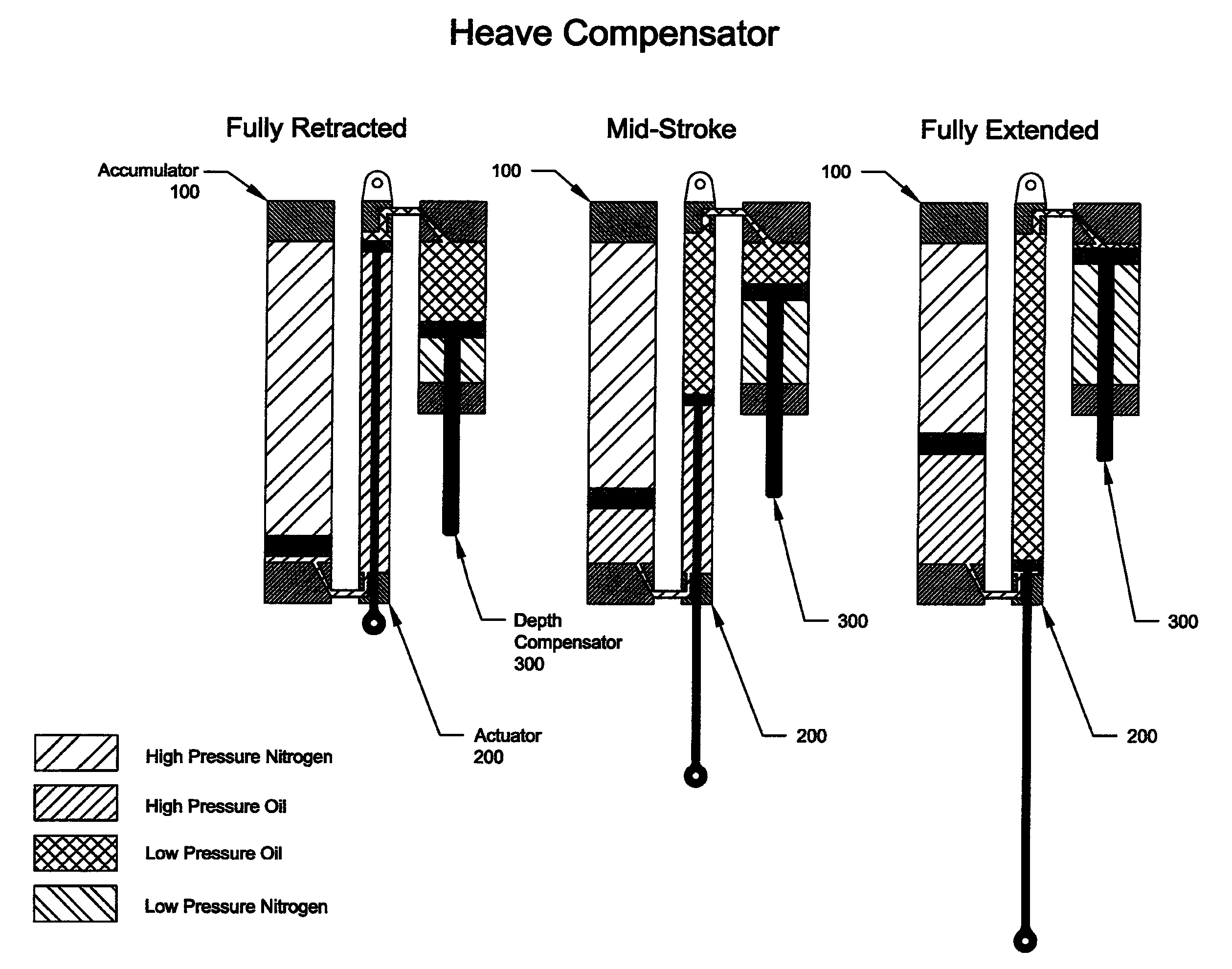
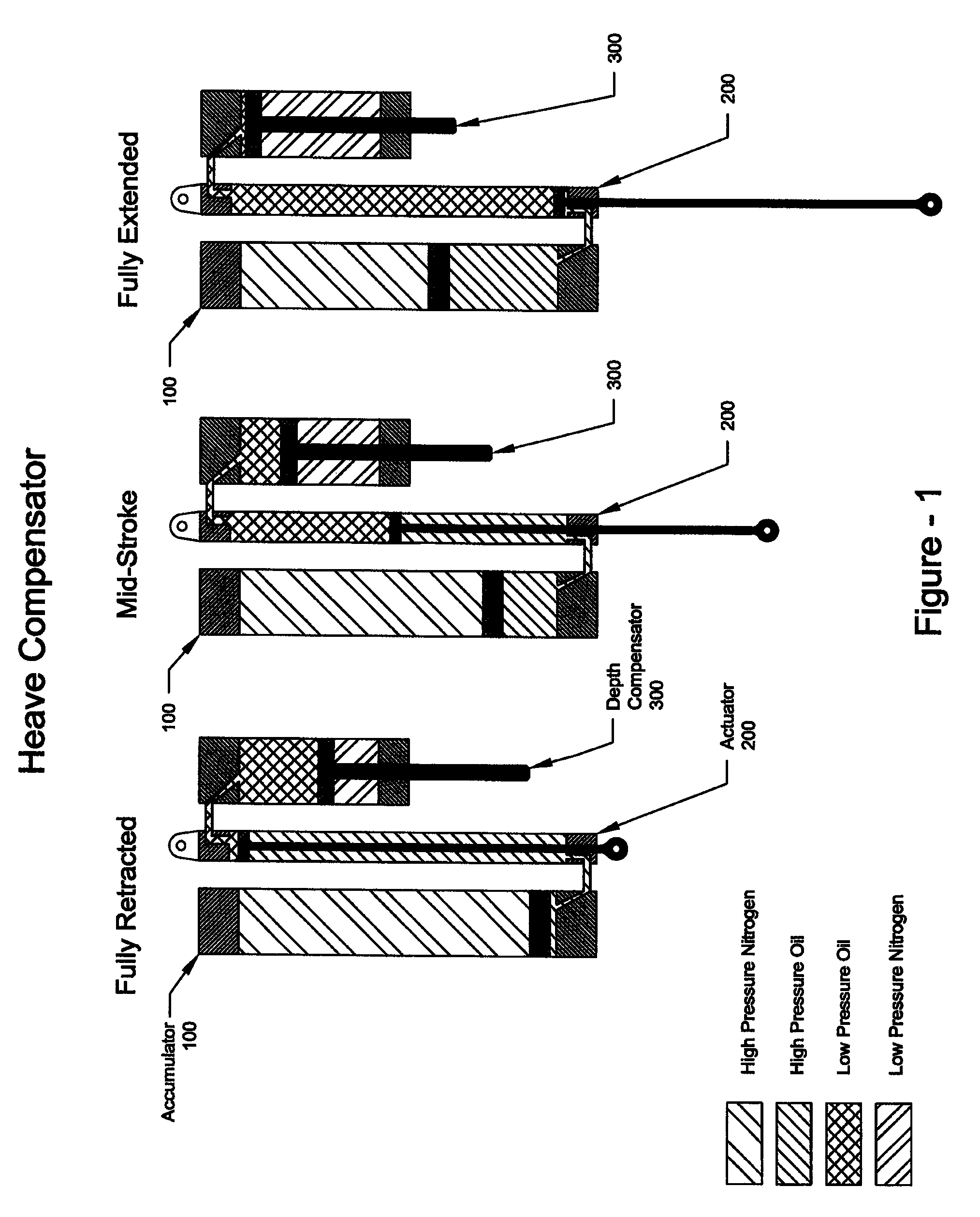
[0010]FIG. 1 is an illustration of the heave compensator with the piston rod in three different positions, retracted, mid-stroke and fully stroked. There are three major components to the heave compensator. To the left is the accumulator 100 the actuator 200 is in the middle and the depth compensator 300 is to the right.

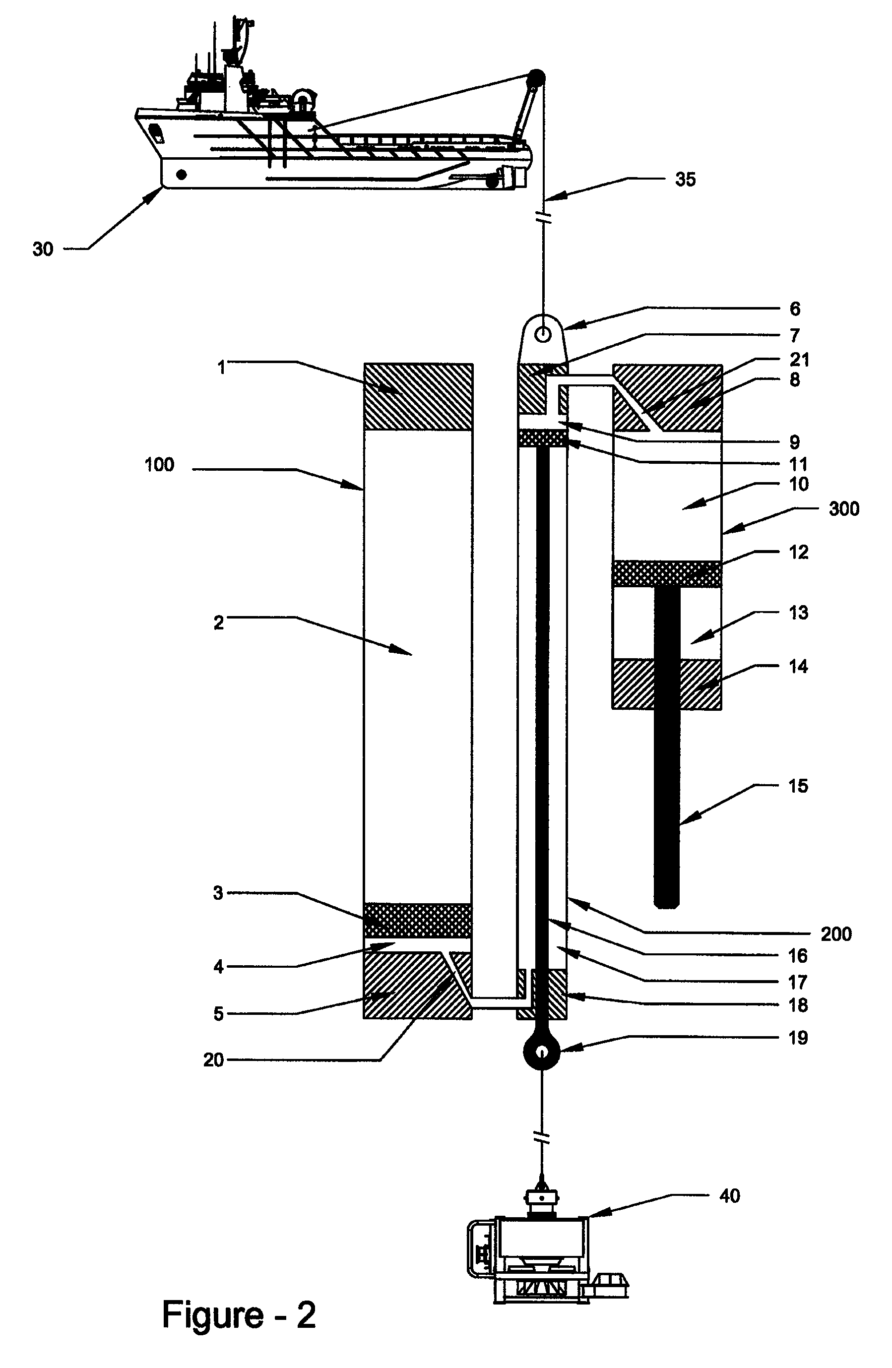
[0011]FIG. 2 illustrates all of the major sub-components numbered 1 through 21. The component description and major-component group is identified in Table 1.

[0012]The Depth Compensated Subsea Passive Heave Compensator (SPHC) is rigged to the vessel 30 at the sea surface via work wire 35 at padeye 6 with 6 facing up and 19 facing down. The subsea equipment 40 is attached to the clevis 19. The accumulator chamber 2 is precharged such that the static position of the rod 16 is mid-stroke when the subsea equipment 40 is submerged. Pod 16 stokes up and down with vessel 30 motion to produce compensation for the subsea equipment 40.

[0013]On the high pressure side, when rod 1...


PUM


Abstract

A depth compensated passive eave compensator comprises a first cylinder connected at its upper end to a vessel. A piston rod extends from a piston located within the first cylinder through the lower end thereof and is connected to subsea equipment. A second cylinder contains a compressed gas which maintains pressure beneath the piston of the first cylinder. The upper end of the first cylinder is connected to the upper end of a third cylinder having a piston mounted therein. A piston rod extending from the piston of third cylinder extends through the lower end thereof thereby applying the pressure of the sea to the piston of the third cylinder.

Description

CROSS-REFERENCE TO RELATED APPLICATION[0001]Applicant claims priority based on provisional patent application Ser. No. 60 / 910,842 filed Apr. 10, 2007, the entire content of which is incorporated herein by reference.BACKGROUND AND SUMMARY[0002]The Subsea Passive Heave Compensator (SPHC) is an installation tool designed to compensate vertical heave during sensitive installation of subsea equipment in an offshore environment. The vertical heave source is typically generated by an installation vessel's motion and or crane tip motion. The SPHC is designed to operate in air or in water at depths up to 10,000 ft. The SPHC is an inline tool that uses the principles of spring isolation to generate a net heave compensation effect or spring isolation effect. The tool is a nitrogen over oil spring dampening device. For spring isolation to occur, the natural period of the spring / mass system must be increased to a ratio higher than the forcing / heave period. Spring isolation begins to occurs when ...

Claims


Application Information

Patent Timeline
Patent Type & Authority Patents(United States)
IPC IPC(8): E21B29/12B66D1/26B63B3/00
CPCE21B19/006F15B1/021F15B1/24B66D1/52F15B21/006F15B15/14F15B2201/205F15B2201/31B66C13/02F16F9/061F16F9/18F16F9/22F16F9/28
Inventor ORMOND, MATTHEW JAKE
Owner INTERMOOR
Why Eureka
Try Eureka