
C-arm mounted on a robotic arm

a robotic arm and c-arm technology, applied in the field of xray devices, can solve problems such as correspondingly complex constructions, and achieve the effects of simple assembly and accessibility, convenient manufacturing, and convenient operation

Active Publication Date: 2011-05-10
SIEMENS HEALTHCARE GMBH
View PDF15 Cites 14 Cited by
  • Summary
  • Abstract
  • Description
  • Claims
  • Application Information

AI Technical Summary

Benefits of technology

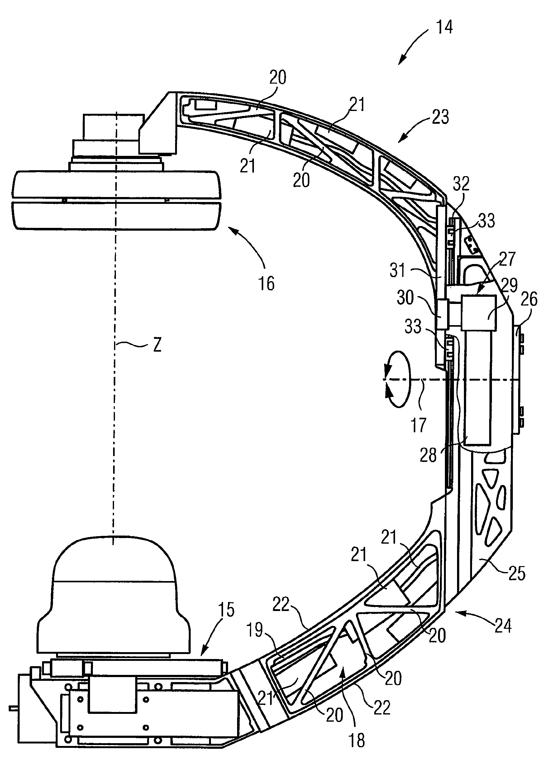
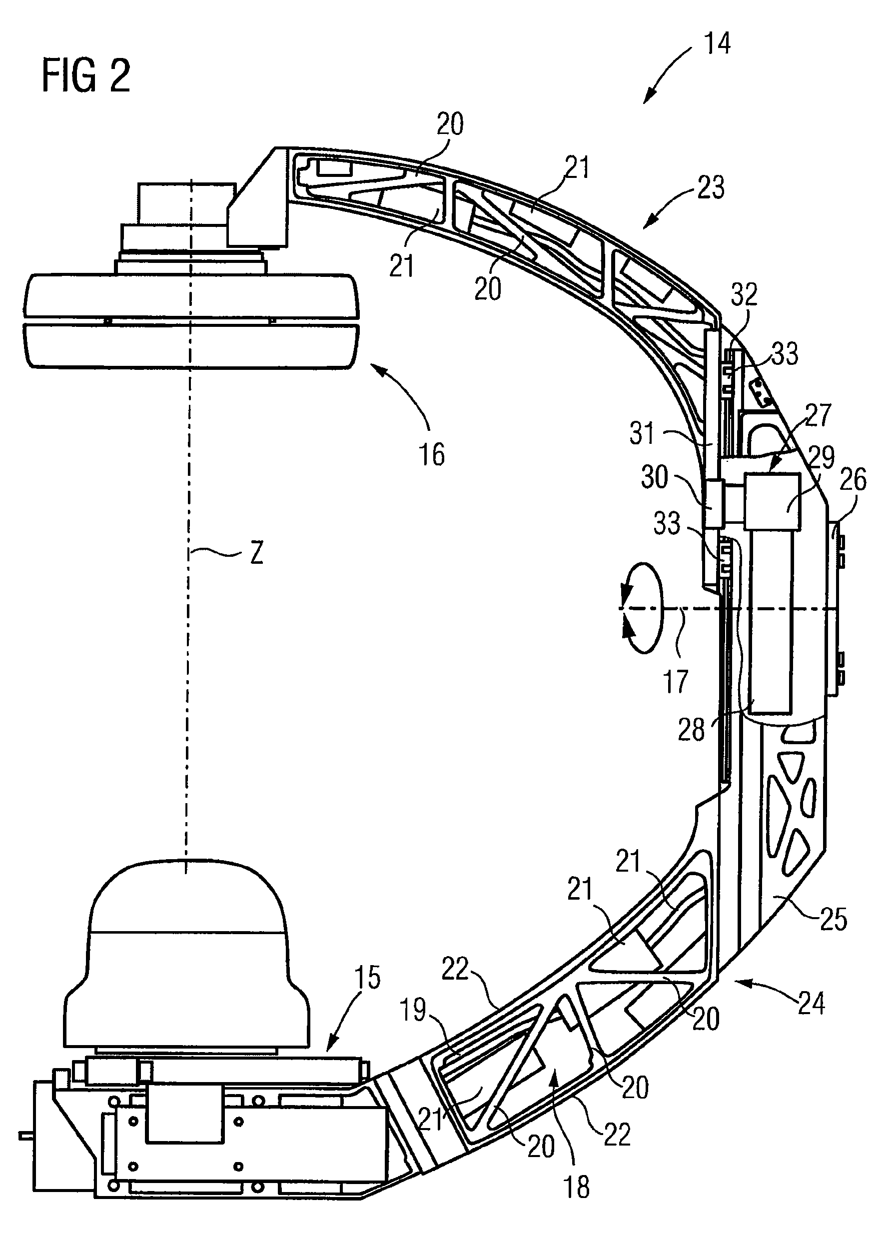
[0007]The x-ray device may include a hollow C-arm that is open from at least one access side. Because the arm is open, at least in sections, on one side or multiple sides, the overall weight of the C-arm is reduced. The C-arm being configured in accordance with the required rigidity and oscillation criteria etc. This criteria can however be maintained and / or achieved despite the open construction. When using the C-arm in conjunction with an industrial robot and / or robotic arm, at least one part or almost all electronic components, which are used to operate the radiation source and radiation detector, may be integrated into the interior of the C-arm. Unlike hollow C-arms with sides that are completely enclosed, the electronic components of the C-arm, which usually involve components or cables with relatively small dimensions, may be positioned in the interior of the arm. The electronic components do not need to be arranged separately and may be connected to the operating components on the floor by, for example, cable or control line connections and are instead moved using the C-arm. The electronic components are relatively light components, as result of their high integration density. In other words, the weight of all the electronic components to be integrated is not too great. As a result, there is only a relatively minimal weight increase in the C-arm so that the requirements still placed on high dynamics can be achieved despite integration of the electronic components.
[0010]The interior of the C-arm may be accessible from access sides, which are arranged opposite to one another. For example, the access sides may be the two side surfaces in the case of a rectangular arm profile, as viewed from the cross-section. The relevant positions on both sides may be reached for assembly or maintenance purposes, thereby facilitating operation. As a result, assembly and accessibility is simple.
[0011]The C-arm may be a framework on one access side. For example, struts may be arranged in the form of a framework on one access side. The framework may be applied to both sides in the case of an arm structure, which is open on both sides. The framework construction may be realized on both sides, which may include the same configuration. The C-arm may be a cast part. As a result, the C-arm may be easily manufactured. The embodiment of the framework structure and / or the arrangement of the struts is selected on the one hand in respect of weight optimization, in order to save as much material as possible. The strut arrangement is designed in order to achieve the desired mechanical properties. Material may be saved primarily in the region of low mechanical stresses and / or loads, whereas in regions of a higher mechanical load, corresponding supports are provided in a suitable angular arrangement in respect of each other and / or other arm sections. The design of the structure conforms with the given geometric and mechanical specifications.
[0013]The, or each, access side may be closed off with a detachable cladding. The detachable cladding may be easily and rapidly removed for assembly or maintenance purposes.
[0015]In one embodiment, a lifting device may be provided. The lifting device may move the radiation detector along the axis of the central beam, such as the axis which connects the radiation source directly to the radiation detector. The film focus distance between the radiation source and radiation detector may be varied. With known devices, the lifting device is positioned directly at the end of the arm on the radiation detector itself, which is not always optimal for weight reasons and in respect of the position of the centre of gravity of the arm. The lifting device also protrudes relatively far, viewed radially, thereby restricting the freedom of movement. With the use of a hollow arm accessible from the side, one expedient development provides for the arm sections to be able to be moved relative to one another by a lifting device which is arranged in the interior of the arm. The open arm allows the lifting device to be integrated into the C-arm. The C-arm may be disposed in the region adjacent to the rotational axis bearing of the C-arm, for example, on the robotic arm, so that the center of gravity can be optimized. The C-arm may lay as close as possible to the axis of rotation, which provides even better movement dynamics. The weight at the end of the arm supporting the radiation detector may not be determined to a significant extent by the lifting device, but instead only by the radiation source located there, since the lifting device is arranged in the interior of the arm on the rotating connection thereof on the robotic arm, for example. The C-arm does not protrude sideways in the region of the radiation detector, instead its form is essentially determined by the geometry of the arm.

Problems solved by technology

This results in correspondingly complex constructions.

Method used


Image

  • C-arm mounted on a robotic arm
  • C-arm mounted on a robotic arm
  • C-arm mounted on a robotic arm

Examples


Embodiment Construction

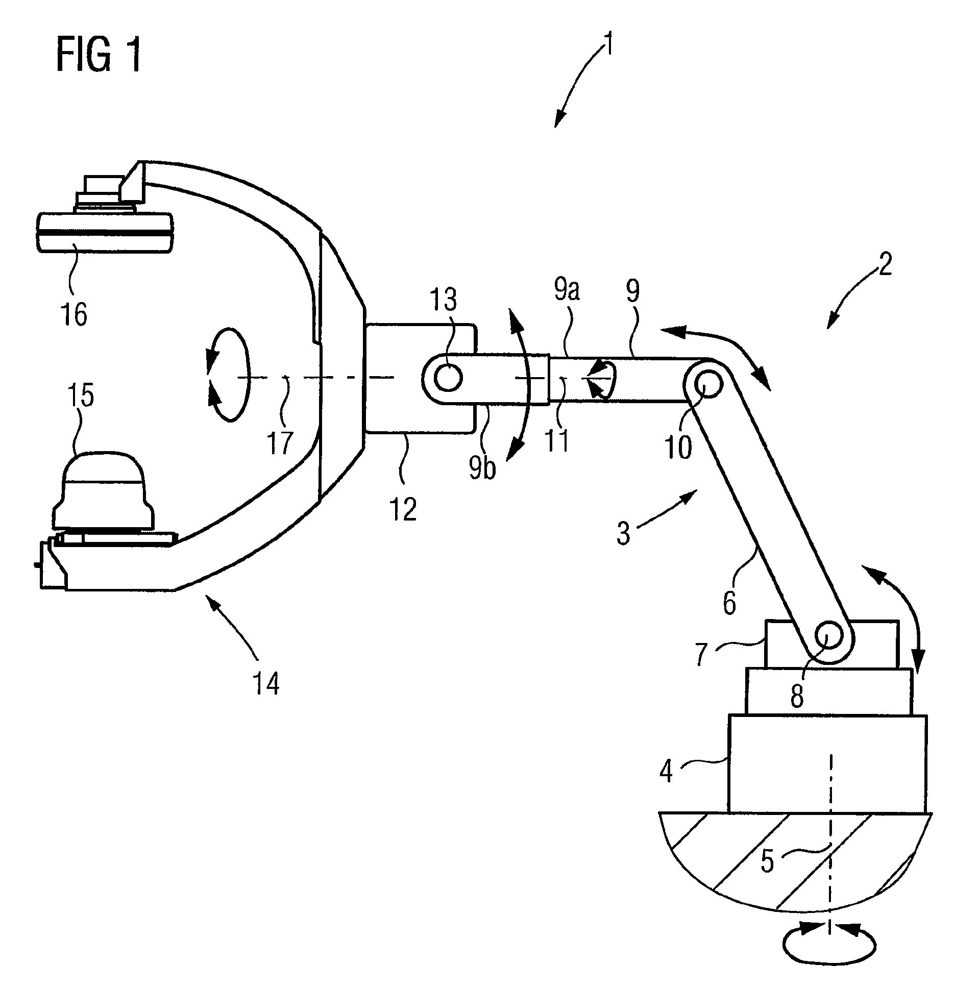
[0022]FIG. 1 shows an x-ray device 1 including an industrial robot 2, with a robotic arm 3, which is accommodated on a base 4, arranged on the floor. The robotic arm 3 is rotatable overall on the base about a vertical axis 5. The robotic arm 3 is accommodated on the base 4 by a first robotic arm 6 on a base part 7. The first robotic arm 6 can be rotated about the vertical axis, on which base part 7 it can also be pivoted about a horizontal axis 8. A second robotic arm 9 is positioned on the first robotic arm 6. The robotic arm 9 may be pivotable thereupon about a second horizontal axis 10. The second robotic arm 9 includes the first arm section 9a, which is arranged on the first robotic arm 6, as well as a second arm section 9b, which for its part can be rotated about a further axis 11 relative to the arm section 9a. A C-arm mount 12, which can be rotated about the axis 13, may be positioned on the arm section 9b. The C-arm 14, upon which a radiation source 15 and a radiation detect...


PUM


Abstract

An x-ray device is provided. The x-ray device includes a C-arm that may be rotatably mounted on a robotic arm. A radiation source and a radiation detector may be arranged on the C-arm. The interior of the C-arm, which is hollow at least in sections, is accessible from at least one access side to allow at least a part of the electronic components used to operate the radiation source and the radiation detector to be integrated in the interior of the arm.

Description

[0001]This patent document claims the benefit of DE 10 2008 003 816.4, filed Jan. 10, 2008, which is hereby incorporated by reference.BACKGROUND[0002]The present embodiments relate to an x-ray device including a C-arm rotatably mounted on a robotic arm.[0003]X-ray devices include a C-arm that is rotatably arranged on an upright stand on the floor by a swivel guide about a conventionally horizontal axis. In the swivel guide, the C-arm is rotatable about an isocenter along the curved swivel guide. A light C-arm is used in order to achieve as effective a dynamic as possible, especially when the C-arm is moved along the swivel guide at considerable speed. For example, an angiography x-ray device may include a C-arm that is moved along the swivel guide at considerable speed. As a result, C-arms made of extruded profiles that have an essentially rectangular hollow profile cross-section are normally used.[0004]The C-arm may be arranged on a robotic arm. Instead of a floor stand with the sw...

Claims


Application Information

Patent Timeline
Patent Type & Authority Patents(United States)
IPC IPC(8): H05G1/02
CPCA61B6/4458A61B6/4441
Inventor GRO.BETA., STEFANHEINL, DIETER
Owner SIEMENS HEALTHCARE GMBH
Learn More