Composite structures for storing thermal energy

a composite structure and thermal energy technology, applied in indirect heat exchangers, lighting and heating apparatuses, instruments, etc., can solve the problems of affecting the structure of the vehicle or component in which it is integrated, affecting the performance of the vehicle, and affecting the performance of the componen

Inactive Publication Date: 2011-05-10
HRL LAB
View PDF8 Cites 22 Cited by
  • Summary
  • Abstract
  • Description
  • Claims
  • Application Information

AI Technical Summary

Benefits of technology

[0028]The method may further include heating the three-dimensional ordered polymer microstructure such that a rigidity thereof is increased.

Problems solved by technology

However, in most thermal storage devices, extra weight is added to a component because heat storage devices cannot support weight and must be bolted onto the supporting structure rather than being part of it.
Pores with a large aspect ratio and small diameter are difficult to form.
Furthermore, heat storage systems may use a graphite felt or metal tank to move heat between an exterior environment and a phase change material; however, the tanks and graphite felt do not support the structure of the vehicle or component in which they are integrated.
Additionally, these materials are not templated from a supporting structure that efficiently uses space to maximize the amount of phase change or thermal storage material to be contained and / or stored while remaining mechanically robust.
However, for such heat exchangers, it may be difficult to fabricate high aspect ratio thin diameter pores with porosity of the desired dimensions.

Method used


Image

  • Composite structures for storing thermal energy
  • Composite structures for storing thermal energy
  • Composite structures for storing thermal energy

Examples


example 1

[0083]1. A 0.142 g section of a polymer scaffold was weighed out.

[0084]2. Capric acid (also known as decanoic acid) is placed in a small Petri dish and heated to 40° C. until melted.

[0085]3. The polymer scaffold is submerged in the molten capric acid until it is fully filled. Then it is removed and placed on a weighing dish to dry.

[0086]4. Any extra capric acid is scraped away with a razor blade.

[0087]After incorporation, the composite had a mass of 0.880 g, corresponding to a material that is 84% by mass capric acid. Since the heated polymer has a density of 1.26 g / cm3 and capric acid has a density of 0.893 g / cm3, this corresponds to a scaffold that is 88 vol % capric acid and 16 vol % polymer scaffold. Top and side views of this composite are shown in FIGS. 10a and 10b, respectively.

[0088]The images in FIGS. 10a and 10b show a well-filled composite material. Here, the side view in FIG. 10b shows a vertical cut through the material, which is why a hexagonal pattern of scaffold rods...

example 2

[0091]1. 0.080 g of a rigid graphite scaffold is weighed out

[0092]2. Capric acid (also known as decanoic acid) is placed in a small Petri dish and heated to 40° C. until melted.

[0093]3. The polymer scaffold is submerged in the molten capric acid until it is fully filled. Then it is removed and placed on a weighing dish to dry.

[0094]4. Any extra capric acid is scraped away with a razor blade.

[0095]After incorporation, the composite had a mass of 0.141 g, corresponding to a material that is 43% by mass capric acid. Since graphite has a density of 2.2 g / cm3 and capric acid has a density of 0.893 g / cm3, this corresponds to a scaffold that is 65 vol % capric acid and 35 vol % polymer scaffold. Top and side views of this composite are shown in FIGS. 12a and 12b, respectively.

[0096]The images in FIGS. 12a and 12b show a well-filled composite material. Here, the side view in FIG. 12b shows a vertical cut through the material, which is why the crosshatch pattern of the scaffold is observed.

[...

example 3

[0099]1. A polymer scaffold and paraffin wax are placed in a vacuum bag.

[0100]2. The bag is heated to 65° C. to melt the paraffin wax, and vacuum is applied to pull the paraffin through the scaffold structure.

[0101]If a scaffold with 90% of its volume being free space is used and it fills completely with wax, this composite will absorb 137 J / g of heat as a result of the paraffin wax melting.


PUM


Abstract

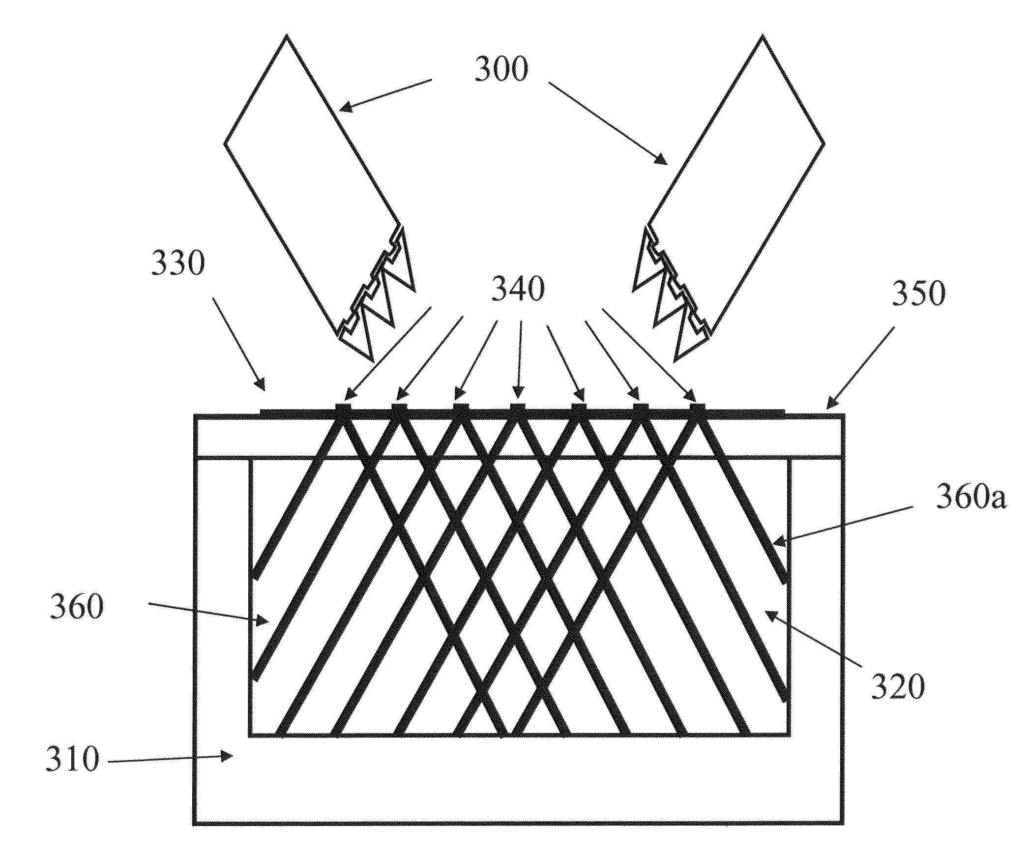
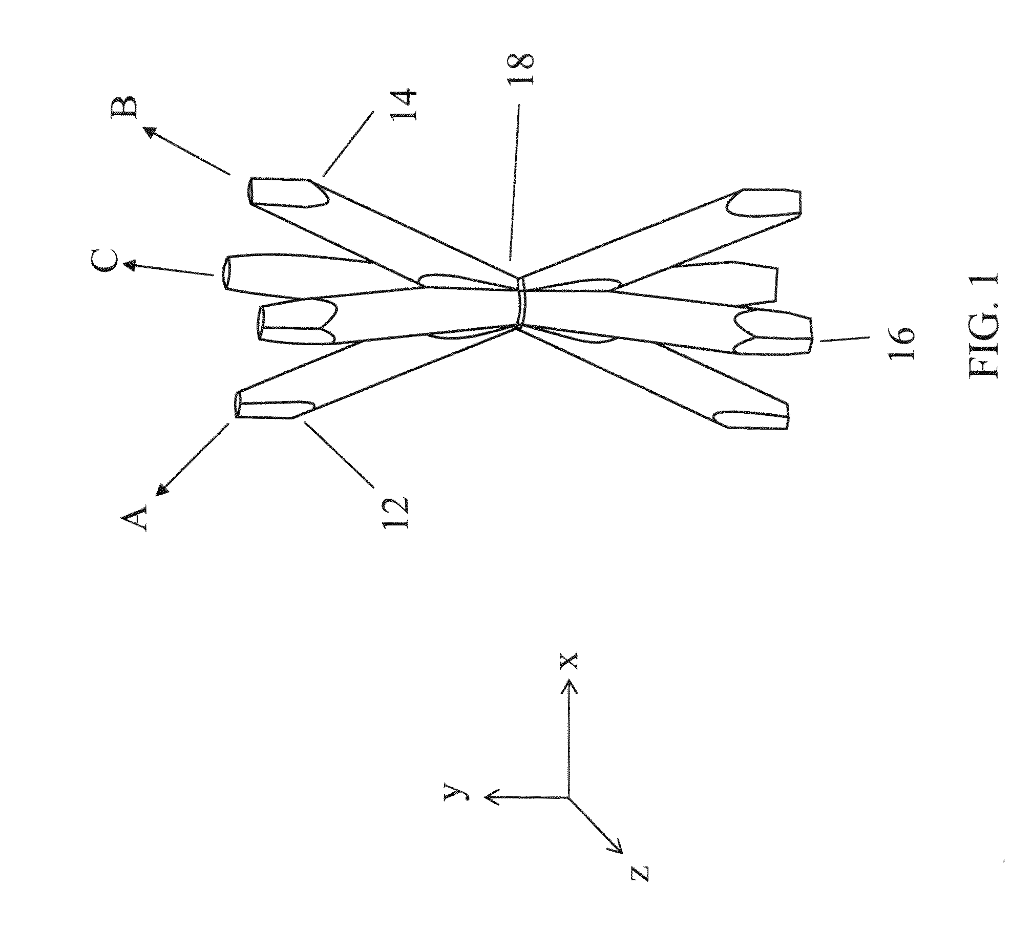
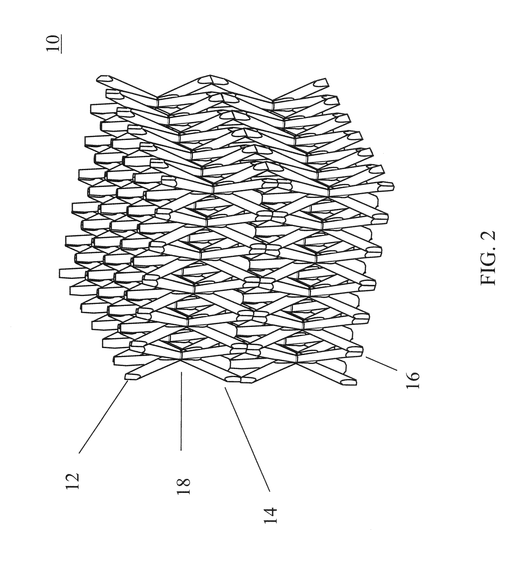
A composite structure for storing thermal energy. In one embodiment, an apparatus for storing thermal energy includes: a thermal storage material and a three-dimensional structure. The three-dimensional structure includes: a plurality of first truss elements defined by a plurality of first self-propagating polymer waveguides and extending along a first direction; a plurality of second truss elements defined by a plurality of second self-propagating polymer waveguides and extending along a second direction; and a plurality of third truss elements defined by a plurality of third self-propagating polymer waveguides and extending along a third direction. The first, second, and third truss elements interpenetrate each other at a plurality of nodes to form a continuous material. The first, second, and third truss elements define an open space. The thermal storage material occupies at least a portion of the open space, and the three-dimensional structure is self-supporting.

Description

CROSS REFERENCE TO RELATED APPLICATION(S)[0001]This application is a divisional of U.S. patent application Ser. No. 12 / 075,033, filed Mar. 6, 2008 now U.S. Pat. No. 7,653,276, the disclosures of which are incorporated fully herein by reference.FIELD OF THE INVENTION[0002]The present invention relates to three-dimensional composite structures for storing thermal energy.BACKGROUND OF THE INVENTION[0003]Heat storage devices can be fabricated from a phase change material that can be a salt hydrate or an organic molecule and a container. The phase change material is placed in a tank or melted into a high thermal conductivity porous structure that is in a container. When the container absorbs heat, the phase change material absorbs the heat and melts if the temperature is above the phase change temperature. When the temperature drops below the phase change temperature, the material goes through a reverse phase change and releases heat. This is advantageous because a reduced weight and sma...

Claims


Application Information

Patent Timeline
Patent Type & Authority Patents(United States)
IPC IPC(8): G02B1/12
CPCF28D20/023Y02E60/145Y02E60/14
Inventor GROSS, ADAM F.FINNILA, RONALD M.JACOBSEN, ALAN J.CUMBERLAND, ROBERTSKEITH, SKY L.
Owner HRL LAB
Why Eureka
Try Eureka