
Partial regeneration in a multi-level power inverter

a power inverter and multi-level technology, applied in the direction of power conversion systems, dc source parallel operation, circuit arrangements, etc., can solve the problems of emi, diode-based rectifiers do not provide the regenerative operating mode, and diode-based rectifiers do not provide control over reactive input current components

Active Publication Date: 2011-05-10
TECO WESTINGHOUSE MOTOR
View PDF42 Cites 49 Cited by
  • Summary
  • Abstract
  • Description
  • Claims
  • Application Information

AI Technical Summary

Benefits of technology

"The present invention is about a system for controlling a medium voltage drive system that includes multiple power cells. The system includes transformers, phase output lines, and at least one controller. The controller can simultaneously control a DC bus voltage, correct a power factor, and provide harmonic current compensation for the system. The system can also include multiple modular transformers that are coupled to regeneration and non-regeneration power cells. The technical effects of the invention include improved efficiency and control of the drive system, as well as reduced harmonic current and improved power factor."

Problems solved by technology

However, this topology requires a large number of isolated DC voltage sources to supply each cell.
However, the supply current to the rectifier contains many harmonic current components, which can be very disturbing for equipment and power systems, and cause electromagnetic interference (EMI).
Besides, the diode-based rectifier does not provide control over the reactive input current component, and the diode-based rectifier does not provide the regenerative operating mode as required, for instance, by downhill belt conveyors in mining applications, where this operating mode is the normal one, as several megawatts are required to be taken back to the AC drive.
Voltage and current harmonics in power transmission and distribution have become a serious problem.
However, to meet the requirements of the IEEE 519 standard, the impedance of the transformer should be high (typically on the order of approximately 8 to 15% PU for medium voltage drives) and a large amount of capacitance must be accommodated in the DC bus of power cells, which make both transformers and power cells bulky and expensive.

Method used


Image

  • Partial regeneration in a multi-level power inverter
  • Partial regeneration in a multi-level power inverter
  • Partial regeneration in a multi-level power inverter

Examples


Embodiment Construction

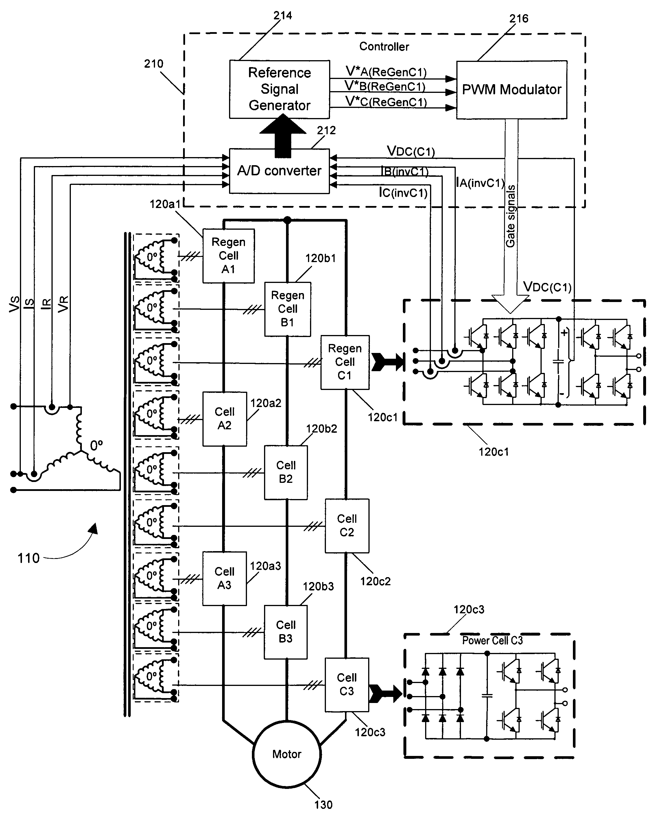
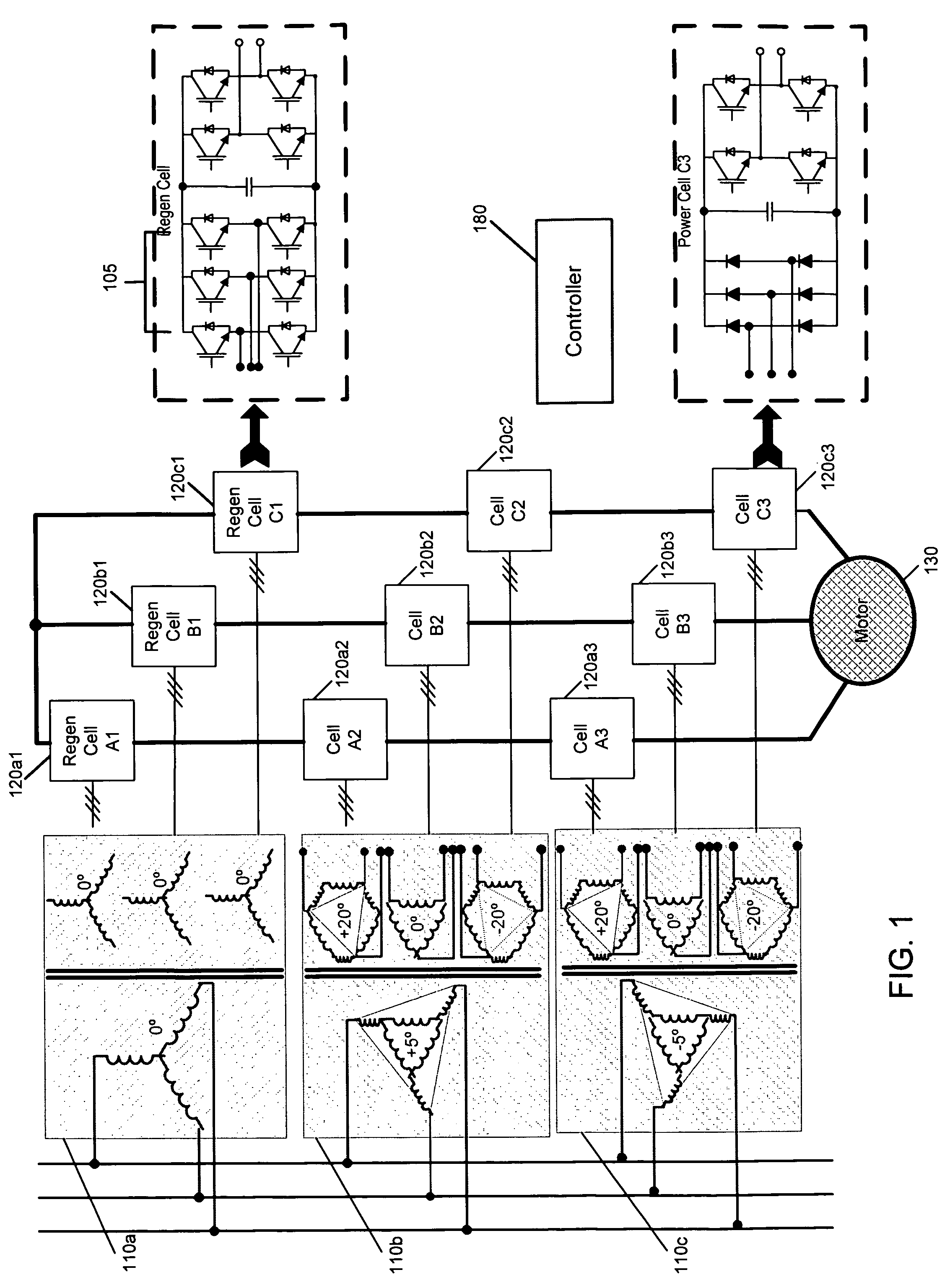
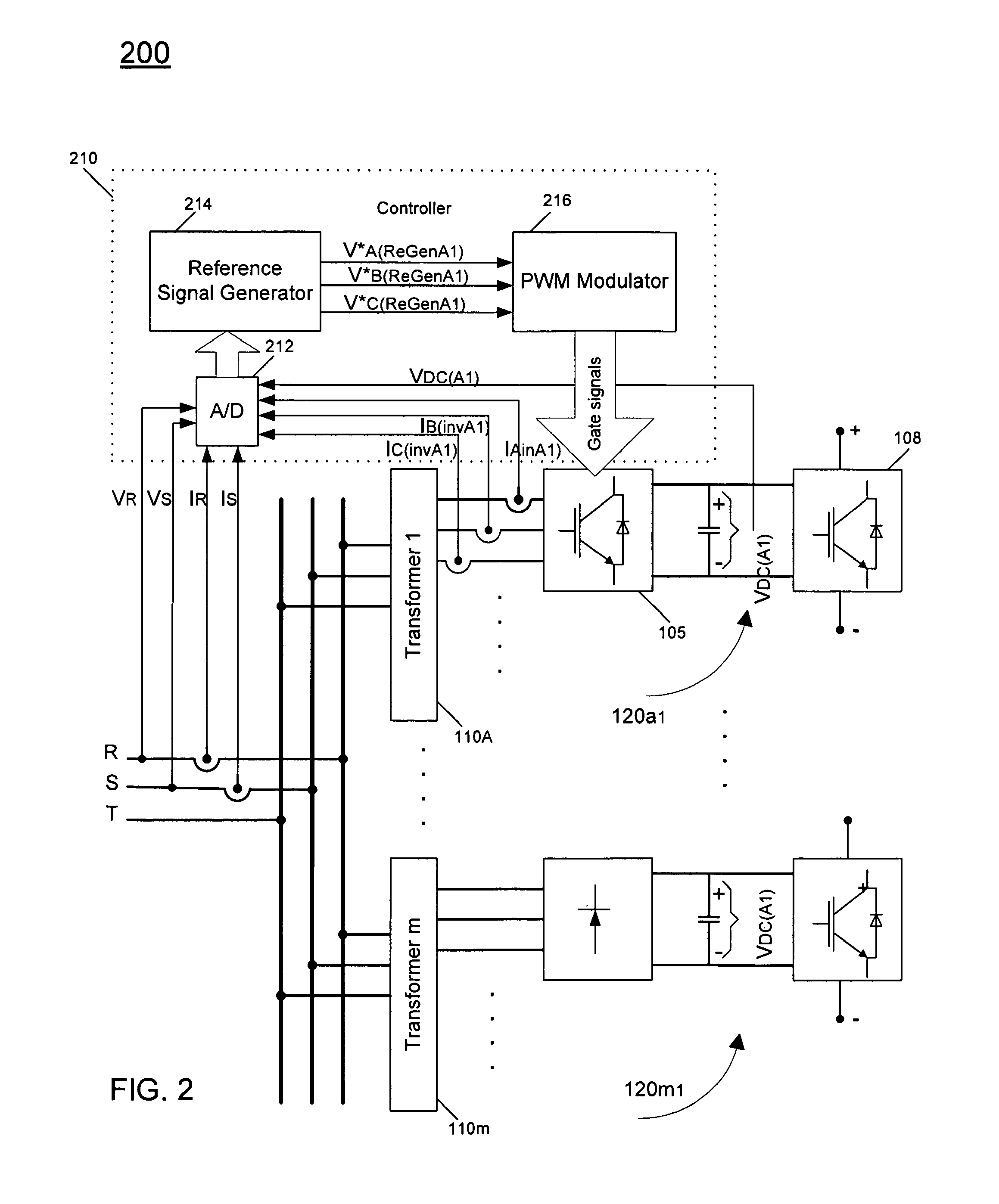
[0016]Embodiments may provide a harmonics current-free partial regenerative high power medium voltage drive. By providing a drive having at least some regenerative power capability, higher performance can be realized in applications that have faster deceleration times. Some implementations can be used for applications such as test benches for motors and transmissions, oil pumps, heavy-duty cranes handling freight containers, centrifuges in food production and process industries, rolling mills, sheet-metal presses, cable-car controls, ski lifts, pump control at water treatment plants, and HVAC chiller control for office buildings. In addition, regenerative power cells of the drive may also perform as an active filter and power factor corrector to compensate for harmonics currents as well as reactive power of the drive, which are generated by non-regenerative (e.g., diode front-end) power cells.

[0017]To enable such regeneration, embodiments may replace a passive (e.g., diode-based) re...


PUM


Abstract

In one embodiment, the present invention includes a medium voltage drive system having multiple power cells each to couple between a transformer and a load. A first subset of the power cells are configured to provide power to the load and to perform partial regeneration from the load, and a second subset of the power cells are configured to provide power to the load but not perform partial regeneration. A controller may be included in the system to simultaneously control a DC bus voltage of at least one of the first subset of the power cells, correct a power factor of the system, and provide harmonic current compensation for the system.

Description

BACKGROUND[0001]Generally, equipment referred to as a power converter, inverter or drive is used to provide power to another piece of equipment such as a motor. Specifically, such a converter (converter is used generally herein to refer to converters, inverters and drives) is coupled to a utility connection to receive incoming input power such as three-phase AC power. The converter conditions the power to provide a conditioned power signal to the equipment to be powered. In this way, incoming power to the equipment may be of improved efficiency, leading to reduced costs to operate the equipment.[0002]Multi-level power converters have been gaining popularity mainly due to improved power quality, lower switching losses, better electromagnetic compatibility, and higher voltage capability. These improvements in power conversion are achieved by using a multiple voltage step strategy. One common multi-level inverter topology is a series H-bridge inverter, in which multiple H-bridge invert...

Claims


Application Information

Patent Timeline
Patent Type & Authority Patents(United States)
IPC IPC(8): H02M1/12
CPCH02M7/49H02M5/4585
Inventor ABOLHASSANI, MEHDIKEISTER, THOMASSKORCZ, ALEXLEDEZMA, ENRIQUEEDWARDS, RYAN
Owner TECO WESTINGHOUSE MOTOR
Learn More