
Electrically conductive composite material

a composite material and electrical conductivity technology, applied in the direction of fuel cells, chain saws, heat measurement, etc., can solve the problems of poor electrical conductivity of polymer composite materials, limited conductivity to the direction of fibers, and limited usefulness of applications, so as to enhance electrical conduction and/or facilitate the formation, the effect of efficient shipping

Inactive Publication Date: 2011-05-24
CONDUCTIVE COMPOSITES CO IP LLC
View PDF30 Cites 43 Cited by
  • Summary
  • Abstract
  • Description
  • Claims
  • Application Information

AI Technical Summary

Benefits of technology

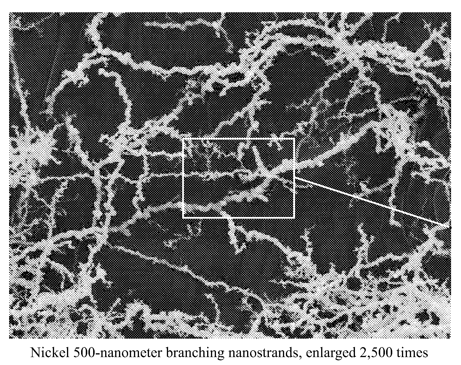
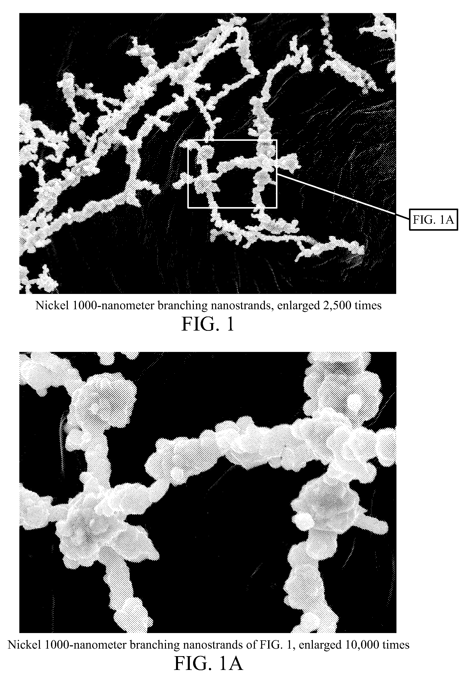
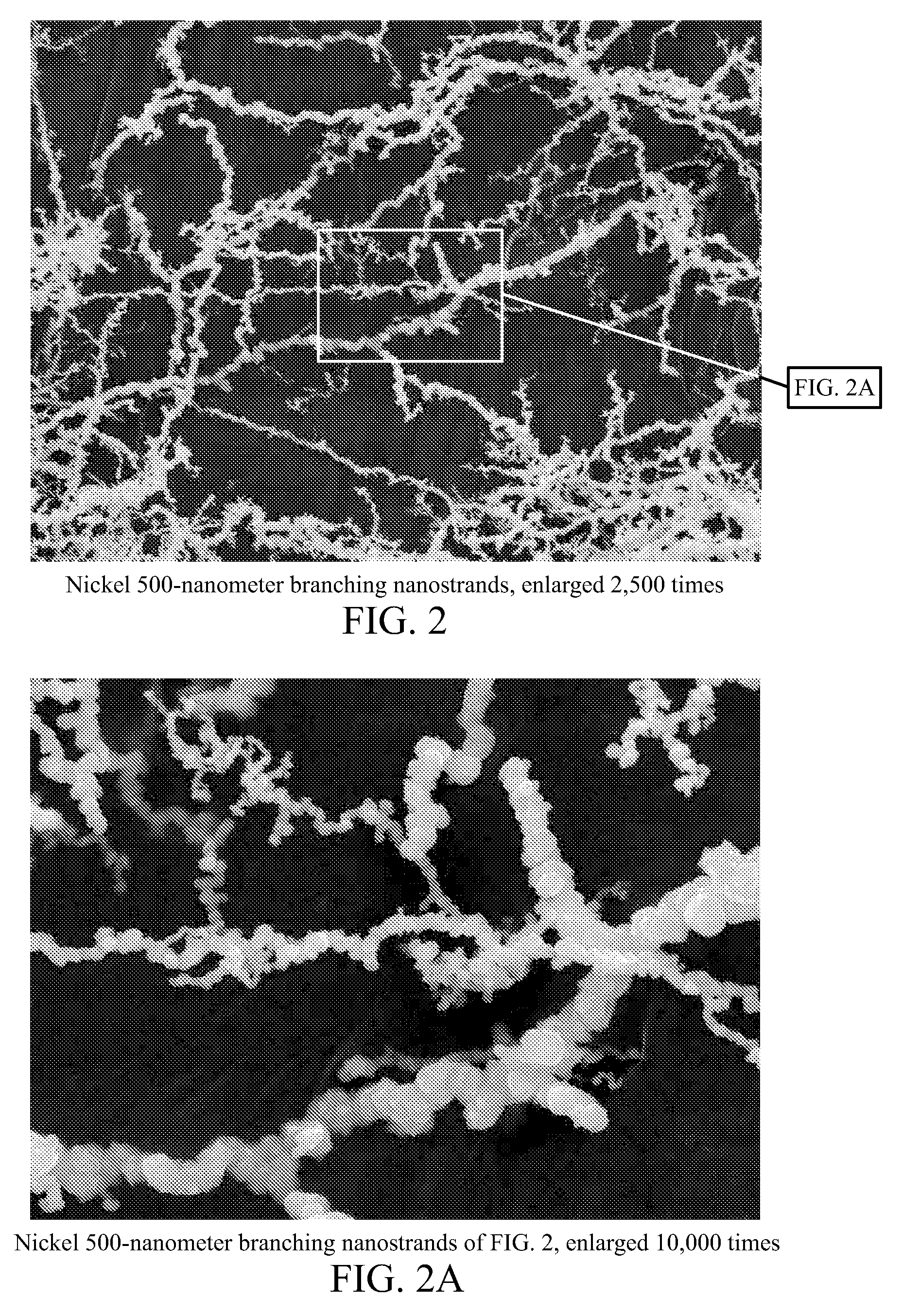
[0014]To achieve the foregoing objective, and in accordance with the invention as embodied and broadly described herein in one embodiment, a composite material may have a matrix formed of a nonmetallic material, which may comprise a polymer, a ceramic, an elastomer, or any combination thereof. Metallic nanostrands are distributed throughout the matrix. The metallic nanostrands may have an average diameter under about four microns and an average aspect ratio (length-to-diameter ratio) of about ten-to-one or greater. The metallic nanostrands may be constructed of a metal such as nickel or iron. The nanostrands may also provide additional mechanical strength and / or thermal conductivity.
[0028]Through the use of the conductive composite materials and methods of the present invention, conductive polymers, elastomers, ceramics, or composite materials having enhanced electrical conduction and / or other properties may be made. Such composite materials may be easily formed in a wide variety of shapes. These and other features and advantages of the present invention will become more fully apparent from the following description and appended claims, or may be learned by the practice of the invention as set forth hereinafter.

Problems solved by technology

However, with the exception of some intrinsically conducting polymers, polymers generally possess poor electrical conductivity.
However, in the case of such composites, the conductivity is limited to the direction of the fibers.
The poor electrical conductivity of such composite materials limits their usefulness in applications such as electromagnetic shielding, circuits, antennas, and the like.
Furthermore, there are many applications in which known polymer-based composites may not be suitable because they do not sufficiently possess properties such as mechanical strength, thermal insulation, stiffness, and hardness.
Known polymer-based composites may not be well suited to applications in which large, constant and / or repeated deflections occur, or applications in which deflection is to be measured.
Yet further, many applications require the use of objects with relatively complex shapes.
Such complex shapes can be difficult or impossible to form from composite materials having the desired electrical conductivity.

Method used


Image

  • Electrically conductive composite material
  • Electrically conductive composite material
  • Electrically conductive composite material

Examples


Embodiment Construction

[0054]The presently preferred embodiments of the present invention will be best understood by reference to the drawings, wherein like parts are designated by like numerals throughout. It will be readily understood that the components of the present invention, as generally described and illustrated in the figures herein, could be arranged and designed in a wide variety of different configurations. Thus, the following more detailed description of the embodiments of the apparatus, system, and method of the present invention, as represented in FIGS. 1-21, is not intended to limit the scope of the invention, as claimed, but is merely representative of presently preferred embodiments of the invention.

[0055]For this application, the phrases “connected to,”“coupled to,” and “in communication with” refer to any form of interaction between two or more entities, including mechanical, electrical, magnetic, electromagnetic, and thermal interaction. The phrase “attached to” refers to a form of me...


PUM

PropertyMeasurementUnit
average diameteraaaaaaaaaa
diameteraaaaaaaaaa
diameteraaaaaaaaaa

Abstract

An electrically conductive composite material includes metallic nanostrands distributed throughout a matrix constructed of a polymer, ceramic, or elastomer. The nanostrands may have an average diameter under four microns and an average aspect ratio over ten-to-one. Larger fibers may also be included to enhance electrical conductivity or other properties. The nanostrands and / or fibers may be magnetically oriented to enhance electrical conductivity along one direction. A pressure sensor may be formed by utilizing an elastomer for the matrix. Electrical conductivity through the composite material varies in proportion to deflection of the elastomer. A composite material may be applied to a surface as an electrically conductive paint. Composite materials may be made by cutting a blank of the nanostrands to the desired shape, inserting the matrix, and curing the matrix. Alternatively, a suspension agent may first be used to dispose powdered nanostrands in the desired shape.

Description

RELATED APPLICATIONS[0001]This application is a divisional of U.S. patent application Ser. No. 10 / 414,266, filed Apr. 15, 2003, and now issued as U.S. Pat. No. 7,935,415, which is related to and claims the benefit of U.S. Provisional Application No. 60 / 373,363 filed Apr. 17, 2002 and entitled METAL NANOSTRAND MATERIAL and U.S. Provisional Application No. 60 / 412,662 filed Sep. 20, 2002 and entitled NICKEL NANOSTRANDS, both of which are incorporated herein by reference.BACKGROUND OF THE INVENTION[0002]1. Field of the Invention[0003]The present invention relates to polymer, elastomer, or ceramic materials or composite materials employing polymers, elastomers, or ceramics as their matrix. More specifically, the present invention relates to the use of metallic nanostrands to form polymers, elastomers, ceramics, or composite materials with enhanced electrical conductivity.[0004]2. Description of Related Art[0005]Polymeric materials, either alone or reinforced with powders or fibers, are a...

Claims


Application Information

Patent Timeline
Patent Type & Authority Patents(United States)
IPC IPC(8): B29C70/10C08K3/08G01R27/08
CPCB29C70/14B29C70/882D04H5/00G01K5/50Y10S977/754G01K2211/00Y10T428/256Y10S977/778Y10T428/249924Y10T428/249933Y10T428/249931
Inventor HANSEN, GEORGE CLAYTONHANSEN, LAURENJENKIN, WILLIAM C.
Owner CONDUCTIVE COMPOSITES CO IP LLC
Learn More