Projector having an adjustment mechanism

a technology of adjustment mechanism and projector, which is applied in the field of projectors, can solve the problems of complex adjustment of optical elements, limited compensation of oblique incident light, and insufficient viewing angle characteristic, etc., and achieves small residual retardation, small retardation, and fine adjustment

Inactive Publication Date: 2011-05-24
SEIKO EPSON CORP
View PDF37 Cites 0 Cited by
  • Summary
  • Abstract
  • Description
  • Claims
  • Application Information

AI Technical Summary

Benefits of technology

[0007]Therefore, an advantage of some aspects of the invention is to provide a projector that can realize a satisfactory contrast and a satisfactory viewing angle characteristic through simple adjustment.
[0017]According to still another aspect of the invention, the first and second optical elements have thicknesses for cooperating to effectively cancel components in a plane parallel to the incidence surface and the emission surface in retardation of liquid crystal due to a liquid crystal present near the incidence surface and the emission surface in the liquid crystal cell. The third optical element has thickness for effectively canceling components in a direction perpendicular to the incidence surface and the emission surface in the retardation of liquid crystal and canceling concomitant retardation concerning the direction perpendicular to the incidence surface and the emission surface due to the first and second optical elements. In this case, it is possible to surely reduce retardation not only in the front direction of the liquid crystal cell but also in a wide range including the vicinity of the front direction of the liquid crystal cell and improve a quality of an image formed by a liquid crystal device.

Problems solved by technology

However, there is a limit in compensation concerning obliquely incident light.
Therefore, a sufficient viewing angle characteristic is not obtained.
However, adjustment of the optical elements is complicated because a number of the optical elements for compensation are increased.
It is difficult to adjust rotating positions of the three optical elements described above because of a space for an adjustment mechanism and complexity of an adjustment process.
Since there are the plural optical elements for compensation between the liquid crystal panel and a projection lens, if adjustment mechanisms are individually provided for the optical elements, a back focus of the projection lens is extended and design of the projection lens is limited.

Method used


Image

  • Projector having an adjustment mechanism
  • Projector having an adjustment mechanism
  • Projector having an adjustment mechanism

Examples


first embodiment

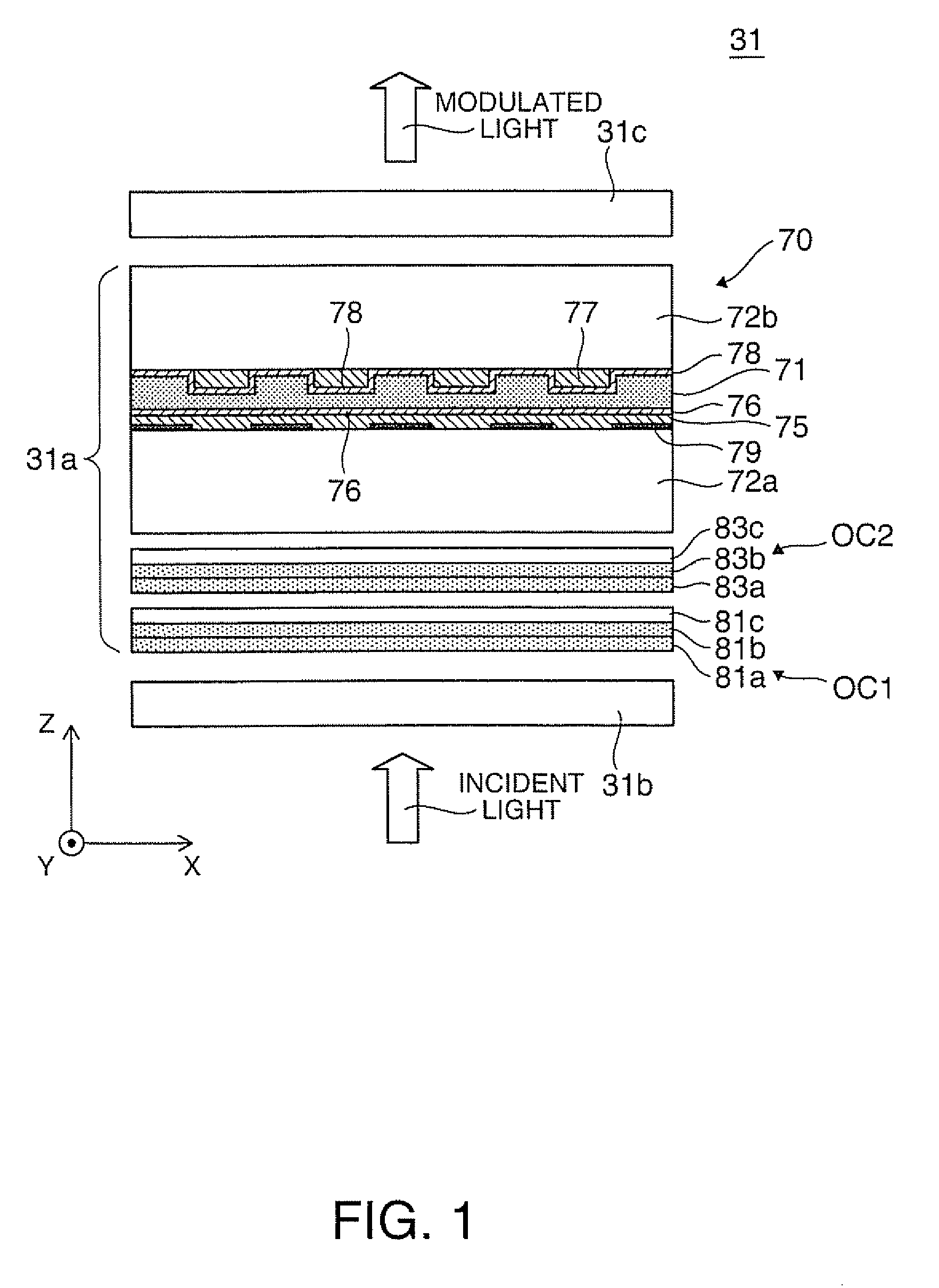
[0031]FIG. 1 is an enlarged sectional view for explaining the structure of a liquid crystal light valve (a light modulator) as a liquid crystal device according to a first embodiment of the invention.

[0032]In a liquid crystal light valve 31 shown in the figure, a first polarization filter 31b as a polarization element on an incidence side and a second polarization filter 31c as a polarization element on an emission side constitute Crossed Nicols. A polarized-light modulating unit 31a between the first and second polarization filters 31b and 31c is a liquid crystal panel that changes a polarization direction of incident light in pixel units according to an input signal.

[0033]The polarized-light modulating unit 31a has a liquid crystal cell 70 including a transparent first substrate 72a on an incidence side and a transparent second substrate 72b on an emission side across a liquid crystal layer 71 including a liquid crystal that operates in a twist nematic mode (i.e., a twist nematic ...

second embodiment

[0061]A liquid crystal light valve as a liquid crystal device according to a second embodiment of the invention is explained below. The liquid crystal light valve according to the second embodiment is a modification of the liquid crystal light valve according to the first embodiment. Components not specifically explained below are the same as those in the first embodiment and redundant explanation of the components is omitted.

[0062]FIG. 9 is an enlarged sectional view for explaining the structure of the liquid crystal light valve according to the second embodiment. In a liquid crystal light valve 131 shown in the figure, the third optical element section 81a is incorporated in the first optical compensation member OC1 of the first group in the polarized light modulating unit 31a. The first and second optical elements 81b and 83b and the third optical element section 83a are incorporated in the second optical compensation member OC2 of the first group.

[0063]FIG. 10 is a diagram for e...

third embodiment

[0066]FIG. 12 is a diagram for explaining the structure of an optical system of a projector incorporating the liquid crystal light valve 31 and the like shown in FIG. 1.

[0067]A projector 10 according to this embodiment includes a light source device 21 that generates light source light, a color separation optical system 23 that divides the light source light from the light source device 21 into three colors of red, green, and bluer a light modulating unit 25 illuminated by illumination lights of the respective colors emitted from the color separation optical system 23, a cross dichroic prism 27 that combines image lights of the respective colors from the light modulating unit 25, and a projection lens 29 as a projection optical system for projecting the image lights transmitted through the cross dichroic prism 27 on a screen (not shown). Among these components, the light source device 21, the color separation optical system 23, the light modulating unit 25, and the cross dichroic pr...


PUM

PropertyMeasurementUnit
twist angleaaaaaaaaaa
angleaaaaaaaaaa
refractive index anisotropyaaaaaaaaaa

Abstract

A projector includes: an optical modulator including a liquid crystal cell, a first optical element formed of an optical material having positive uniaxiality, a second optical element formed of an optical material having positive uniaxiality, a third optical element including at least one optical film formed of optical material having a refractive index anisotropy, and a pair of polarization elements; an adjustment mechanism that can adjust an optical azimuth of a first group, having at least one of the first optical element, second optical element, and at least one optical film included in the third optical element, with respect to a fixed optical azimuth of a second group as a remainder excluding the element included in the first group among the first to third optical elements; a light source generating light for illuminating the optical modulator; and a projection optical system projecting the light passed through the optical modulator.

Description

BACKGROUND[0001]1. Technical Field[0002]The present invention relates to a projector incorporating a liquid crystal device for image formation.[0003]2. Related Art[0004]As a liquid crystal projector in the past, there is a liquid crystal projector employing a twist nematic liquid crystal panel. In the liquid crystal projector, two optical elements for compensation including uniaxial elements having optical axes, which orient a rubbing direction and tilt by a predetermined angle with respect to an incidence surface, are arranged between the liquid crystal panel and an incident side polarizer and between the liquid crystal panel and an emitting side polarizer (see JP-A-2004-198650). In such a liquid crystal projector, it is possible to compensate for a pre-tilt of a liquid crystal by adjusting the optical axes and the thickness of the optical elements for compensation arranged near the liquid crystal panel. Hence it is possible to improve a contrast.[0005]However, when, for example, i...

Claims


Application Information

Patent Timeline
Patent Type & Authority Patents(United States)
IPC IPC(8): G02F1/1335
CPCG02F1/133632H04N9/3197H04N9/3105
Inventor YANAI, HIROAKIENDO, TAKASHI
Owner SEIKO EPSON CORP
Why Eureka
Try Eureka