Cartridge for remote electroshock weapon

a technology of electric wire and battery pack, which is applied in the direction of weapons, small arms, firearms, etc., can solve the problems of inconvenient assembly, inability to apply this device to launching electric wire from a handheld remote weapon to strike various targets, and undesirable barrels

Inactive Publication Date: 2011-05-31
LAW ENFORCEMENT ASSOC
View PDF13 Cites 59 Cited by
  • Summary
  • Abstract
  • Description
  • Claims
  • Application Information

AI Technical Summary

Benefits of technology

[0014]The present invention is aimed at solving the challenge of creating a miniaturized unitary cartridge for launching electric wire for use in a handheld remote electroshock weapon, in which it is the minimum proportions of the cartridge that determine the overall size and weight parameters. Minimization of the cart

Problems solved by technology

The deficiencies of the device are its substantial girth, which makes it impossible to apply this device to launching electric wire from a handheld remote weapon to strike various targets, particularly in modern handheld remote electroshock devices such as the “Air Taser” made by Stinger Systems.
In a remote electroshock weapon, a barrel is in fact undesirable due to the insignificant muzzle energy required, the modest requirements as to fire dispersion, and the high demands as to the weapon's compactness due to the placement within it—besides the launching apparatus—of an electrical device producing electrical impulses that hit the target.
Thus the concept of “cartridge of a remote electroshock weapon” falls under the concept of the “dual cartridge” or “dual cartridge containing barrel within it”, in which the individual firing elements such as the “primer”, “propellant charge”, “projectile”, and the key supplemental element needed for the projectile in a remote electroshock weapon—the “packed electric wire”—are all located within the same housing, but the assembly is extremely inefficient compared to the uni

Method used


Image

  • Cartridge for remote electroshock weapon
  • Cartridge for remote electroshock weapon
  • Cartridge for remote electroshock weapon

Examples


Embodiment Construction

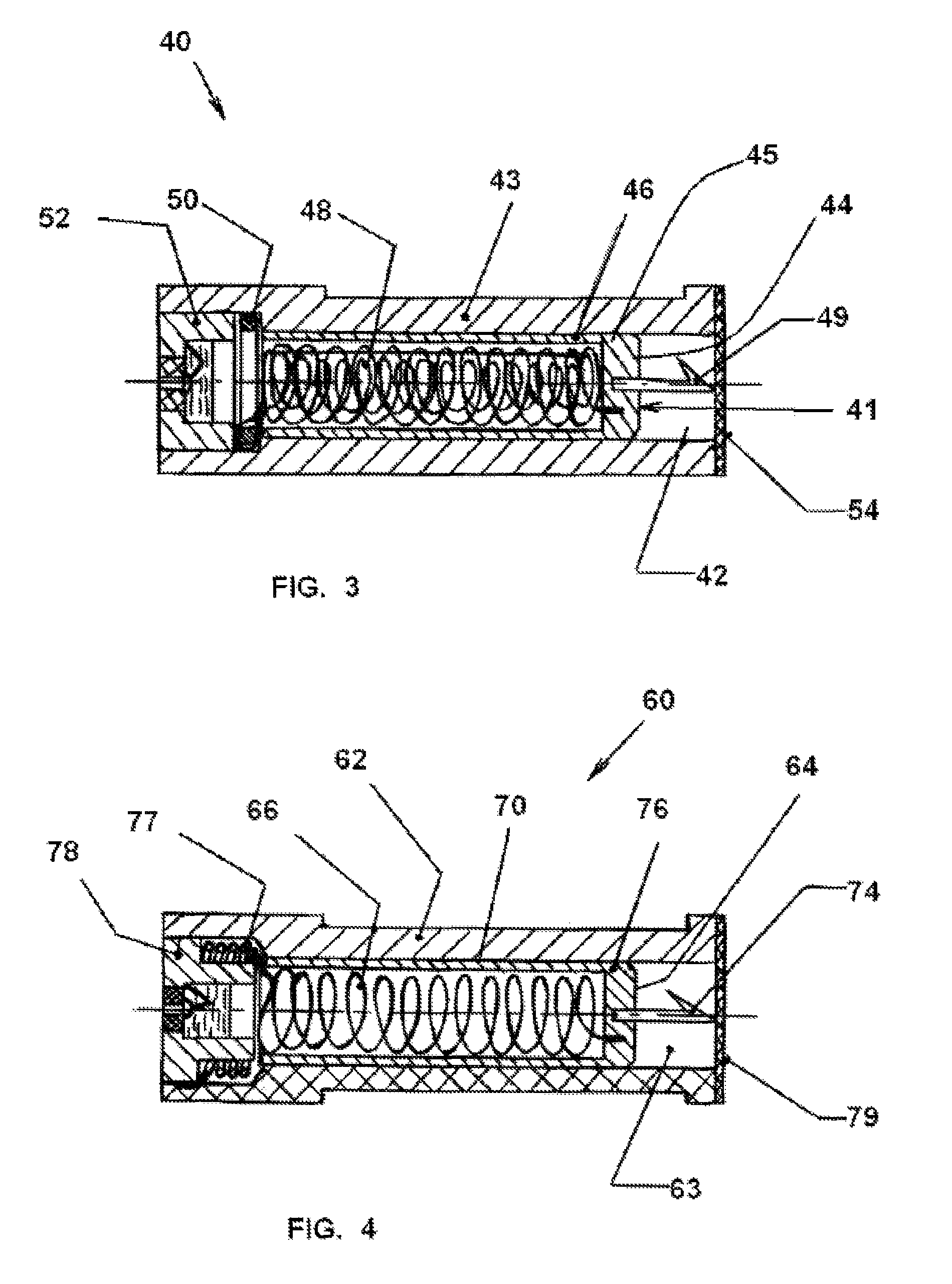
[0044]Depending on the type of electroshock weapon used and the technological capabilities, different variations of the cartridge may be applied.

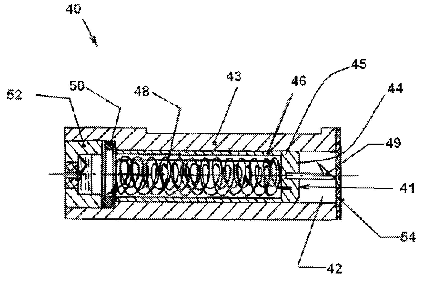
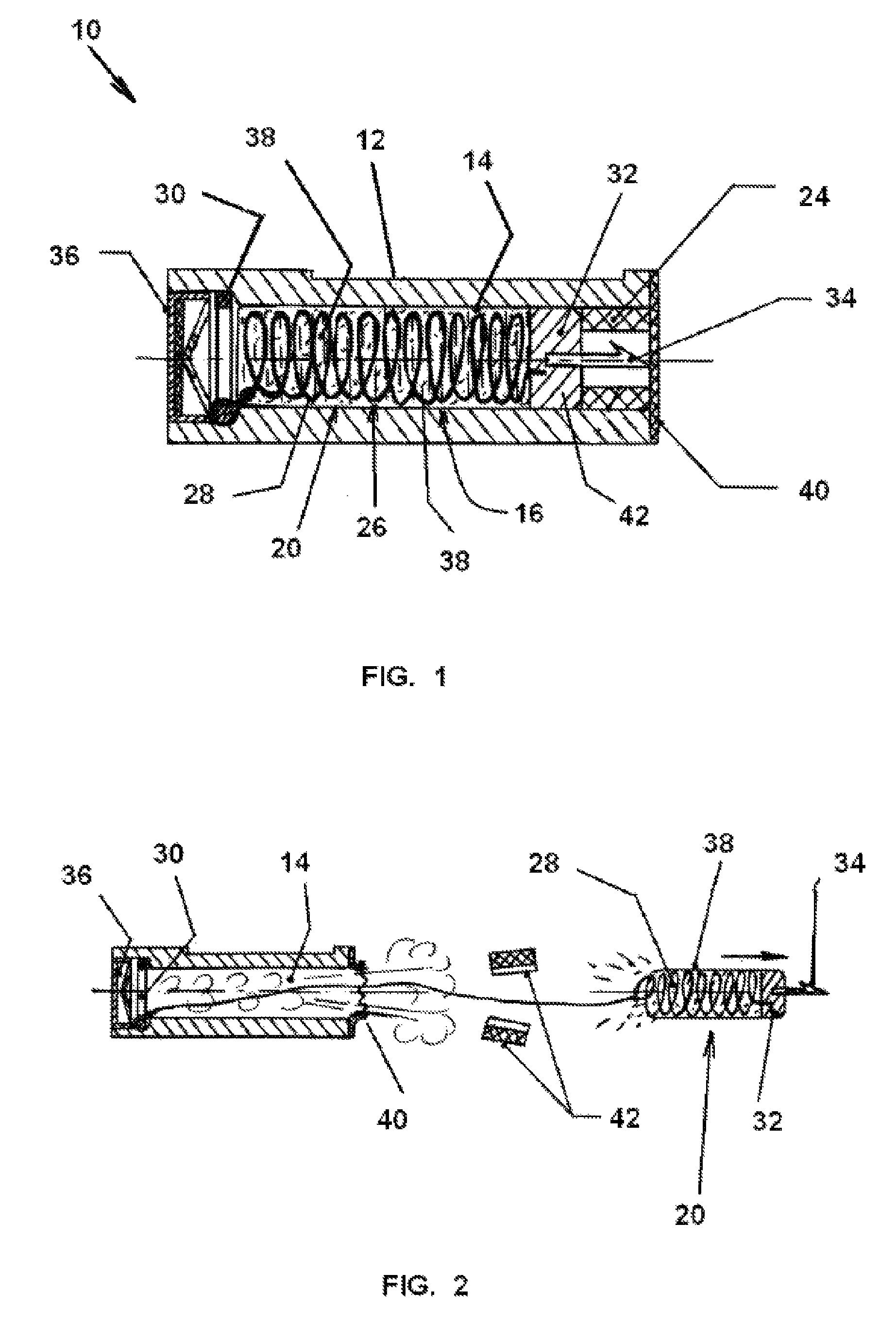
[0045]Referring to FIG. 1, a cartridge 10 for use with a suitable electroshock weapon, not shown, includes a metal casing or housing 12, of rectangular or circular cross section, having an axial chamber 14 carrying a projectile unit 16. The chamber of the housing 12 also forms the barrel, for launching or firing the projectile unit 16.

[0046]The projectile unit 16 comprises an electric wire assembly 20, a head assembly 22. A split sleeve assembly 24 is located in the chamber 14 in front of the projectile unit 16. The electric wire assembly 20 includes a coil 26 of electrical wire 28 connected, by soldering or beading, at one end to the head assembly 22 and at the other end to an annular ring or washer 30. The coil 26 is in the form of a compact single-layer, multi-layer or hybrid self-supported wire.

[0047]The head assembly 22 includes a cyli...


PUM


Abstract

A cartridge for launching from an electroshock weapon includes a housing adapted for operative connection with the electroshock weapon and having a chamber functioning as a barrel for a projectile unit. The projectile unit includes a conductive head member and an orderly packed wire assembly of electric wire connected with said head member and preferably in coil form. The head member includes a barbed needle for establishing an electrical connection with a target. The electric wire is connected at one end to the head member and at the other end to the housing whereby the wire is withdrawn from the coil as the projectile unit advances toward said target. The project unit is launched by a percussive cap at a rear end of said chamber ignited by the electroshock weapon. At the target an electrical connection is established through the wire to the weapon.

Description

FIELD OF THE INVENTION[0001]The invention relates to devices for launching electric wire for remotely impacting various targets with electric current, and more particularly to a unitary cartridge for launching electric wire from a weapon for remote impact on various targets and thereafter delivering an electric current transmitted along the electric wire for use with a remote electroshock weapon.BACKGROUND OF THE INVENTION[0002]Devices for launching weapons attached to a wire for conducting electricity to the impart target are well know. An early version is the “Electric Whaling Apparatus” as disclosed in U.S. Pat. No. 8,843 wherein a harpoon is electrically connected to an electric cable which, when the harpoon is thrown, unwinds from a coil stowed next to the harpoon thrower or cannon. The deficiencies of the device are its substantial girth, which makes it impossible to apply this device to launching electric wire from a handheld remote weapon to strike various targets, particula...

Claims


Application Information

Patent Timeline
IPC IPC(8): F42B5/02
CPCF42B5/02F41H13/0025F42B12/36
Inventor NEMTYSHKIN, OLEGLADYAGIN, YURY
Owner LAW ENFORCEMENT ASSOC
Why Eureka
Try Eureka