Infrared imaging sensor

a sensor and infrared technology, applied in the field of infrared imaging sensors, can solve the problems of large and expensive boilers, limited pulp mill capacity, and difficult economic addition of small incremental units of boiler capacity, and achieve the effect of low cos

Inactive Publication Date: 2011-06-07
VALMET AUTOMATION OY
View PDF11 Cites 24 Cited by
  • Summary
  • Abstract
  • Description
  • Claims
  • Application Information

AI Technical Summary

Benefits of technology

[0013]The invention includes a focal plane array camera capable of creating images in a particular range of infrared radiation that has low absorption by molecules in the gas stream in a chemical recovery boiler or other high temperature process equipment, and is not scattered significantly by particles normally present in the gas in the process equipment. Another aspect of the invention is a system of one or more deposit monitoring sensors feeding signals to a data processing system under control of a distributed control system. Preferably, the deposit monitoring sensors include focal plane array cameras operating in the mid-infra-red band, in the region of about 4-12 microns wavelength. Clear images can be obtained at a low cost of the boiler interior and particularly of the pendant water and steam tubes in the boiler to enable for the first time a visual real time inspection of the condition of the tubes and depositions thereon so that control schemes can be implemented.

Problems solved by technology

Kraft chemical and energy recovery boilers, in which the black liquor is burned, are large and expensive, with capacities installed in the last 30 years for pulp mills typically exceeding 1000 tons of pulp per day.
It is difficult economically to add small incremental units of boiler capacity, so the capacity of the chemical recovery boiler is often the factor limiting the capacity of the entire pulp mill.
However, there are still no reliable on-line methods for systematically detecting the presence and build-up rates of these deposits.
These control efforts are most effective when they are immediately correlated to the results they are intended to produce, but heretofore there has been no reliable method of determining directly the amount of deposits on the pendant tubes.
Such control efforts have therefore necessarily been based on indirect measurements and considerations, and have usually yielded unsatisfactory results.
The severe environment of boilers, namely the high temperature, turbulent gas flow, particle laden atmosphere, and intensity of radiation have made it difficult to develop a sensing system for detection and control of deposition on pendant tubes in Kraft recovery boilers that would be economically viable as a commercial product.
Attempts to use near-IR cameras for direct monitoring of pendant tube deposits have failed to reliably produce good images over the span of large boilers, and devices operating at longer wavelengths have been impractical for boiler-side use because of prohibitive expense and the need for reliable cryogenic cooling.

Method used


Image

  • Infrared imaging sensor
  • Infrared imaging sensor
  • Infrared imaging sensor

Examples


Embodiment Construction

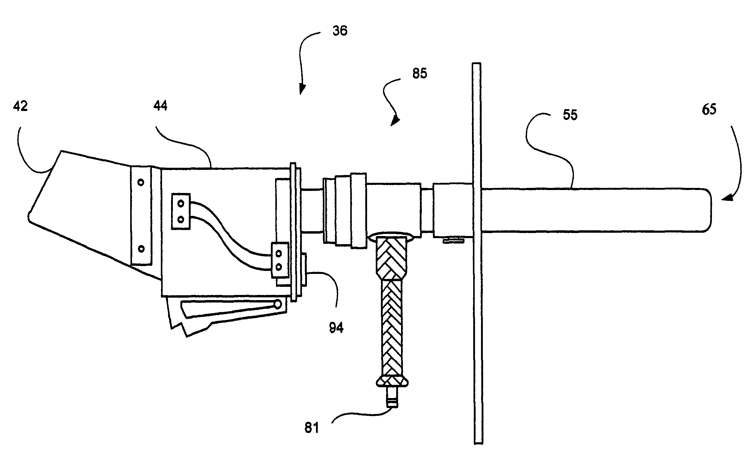
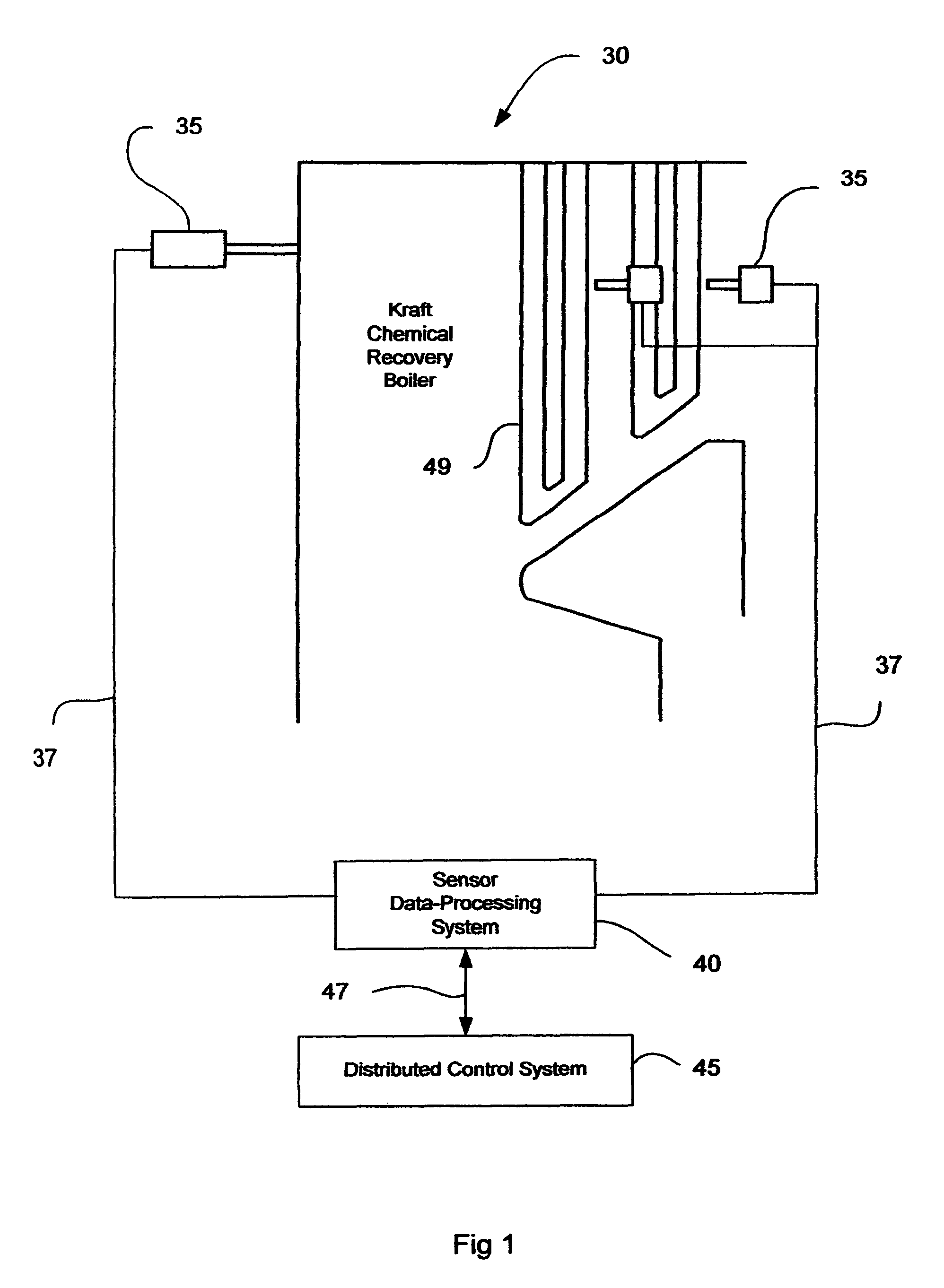
[0025]Turning now to the drawings, and more particularly to FIG. 1 thereof, a deposition detection system in accordance with this invention is shown installed in a Kraft recovery boiler 30. The deposition detection system includes one or several monitoring sensors 35, described in detail below, which acquire data in the midband infra-red spectrum within a particular field of view from the interior of the recovery boiler. The monitoring sensors 35 could be fixed in position to permanently monitor particular areas within the boiler, or could be integrated hand-held units 36 shown in FIG. 3.

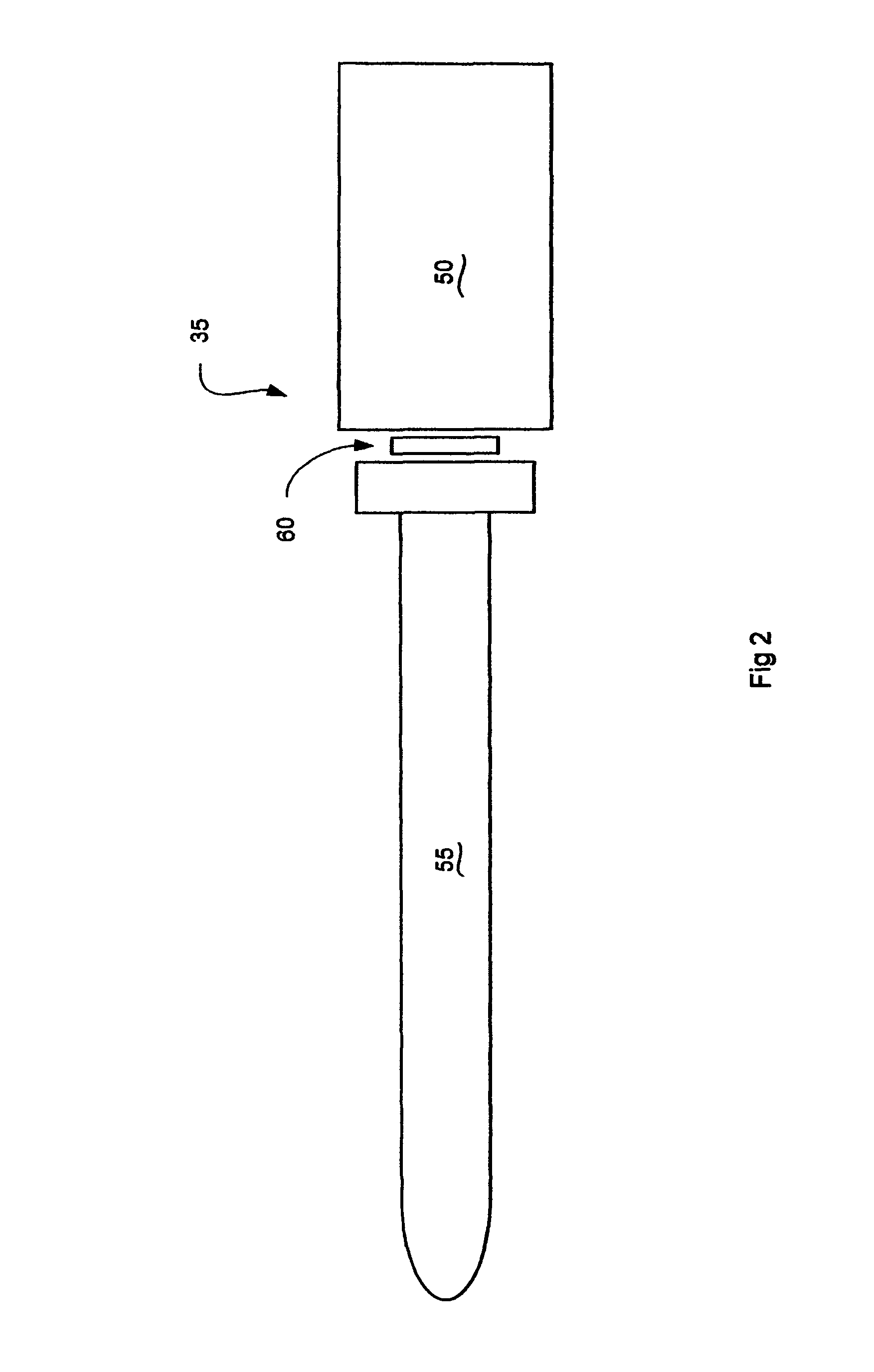
[0026]The sensor 35, shown in more detail in FIGS. 2 and 5-7, converts the acquired infrared data to electrical signals, which are conducted via electrical lines 37 to a sensor data processing system 40, shown in more detail in FIG. 10 and described in detail below. The hand-held sensor 36 shown in FIG. 3 converts the acquired infrared data directly to an image that is viewed on a display inside a h...


PUM


Abstract

A system for detection and control of deposition on pendant tubes in recovery and power boilers includes one or more deposit monitoring sensors operating in infrared regions of about 4 or 8.7 microns and directly producing images of the interior of the boiler, or producing feeding signals to a data processing system for information to enable a distributed control system by which the boilers are operated to operate said boilers more efficiently. The data processing system includes an image pre-processing circuit in which a 2-D image formed by the video data input is captured, and includes a low pass filter for performing noise filtering of said video input. It also includes an image compensation system for array compensation to correct for pixel variation and dead cells, etc., and for correcting geometric distortion. An image segmentation module receives a cleaned image from the image pre-processing circuit for separating the image of the recovery boiler interior into background, pendant tubes, and deposition. It also accomplishes thresholding/clustering on gray scale/texture and makes morphological transforms to smooth regions, and identifies regions by connected components. An image-understanding unit receives a segmented image sent from the image segmentation module and matches derived regions to a 3-D model of said boiler. It derives a 3-D structure the deposition on pendant tubes in the boiler and provides the information about deposits to the plant distributed control system for more efficient operation of the plant pendant tube cleaning and operating systems.

Description

[0001]This application is a Continuation-in-Part, and claims the benefit of, U.S. patent application Ser. No. 11 / 137,089 filed on May 24, 2005, which application issued as U.S. Pat. No. 7,437,025 on Oct. 14, 2008, and which was a divisional application of, and claimed the benefit of, U.S. application Ser. No. 10 / 168,277 filed on Jun. 14, 2002 which issued on Jun. 21, 2005 as U.S. Pat. No. 6,909,816.[0002]This invention pertains to an infrared sensing for inspecting equipment condition and operation in the interior of high temperature process equipment, and more particularly to a mid-band infra-red imaging system that is tuned to a particular spectrum of infra-red radiation to see into the otherwise visually impenetrable interior of high temperature process equipment.BACKGROUND OF THE INVENTION[0003]In 1995, about 82% of the wood pulp consumed at US paper and paperboard plants was produced using the Kraft process. Although the proportion of pulp from this source is likely to decline ...

Claims


Application Information

Patent Timeline
Patent Type & Authority Patents(United States)
IPC IPC(8): G01J5/02
CPCG01N17/008G01J2005/0077
Inventor KYCHAKOFF, GEORGEAFROMOWITZ, MARTIN A.HOGLE, RICHARD E.
Owner VALMET AUTOMATION OY
Why Eureka
Try Eureka