
Thin film structures with negative inductance and methods for fabricating inductors comprising the same

a thin film structure and negative self-inductance technology, applied in the field of passive electronic devices, can solve the problems of eliminating self-inductance, parasitic inductance of high-speed integrated circuits and semiconductor devices, and field able to adversely affect voltage stability,

Active Publication Date: 2011-06-07
UNIV OF DAYTON
View PDF12 Cites 3 Cited by
  • Summary
  • Abstract
  • Description
  • Claims
  • Application Information

AI Technical Summary

Problems solved by technology

High-speed integrated circuits and semiconductor devices are known to suffer from parasitic inductances that occur, for example, in individual components and around interconnection lines.
This time-varying magnetic field is capable of adversely affecting the voltage stability in that component through self-inductance, or in other nearby components through mutual inductance.
Though mutual inductance effects can be obviated, for example, by shielding of some kind, elimination of self-inductance, in particular parasitic self-inductance, remains a challenge.
Parasitic inductance refers to a phenomenon, whereby the magnetic fields generated by component conductors induce undesirable electronic effects.
The occurrence of parasitic inductance acts as a serious performance-limiting factor to integrated circuits and semiconductor devices.
For example, parasitic inductance can degrade signal quality, cause circuit noise and signal ringing, induce voltage drops (Ldi / dt) in the components, and result in loss of data.
Parasitic inductances affect the high-speed performance of circuits by influencing the impedance of components in the circuit.
Such arrangements may comprise multiple components, including field effect transistors (FETs), or complex integrated circuits such as operational amplifiers (op-amps), all of which require a large amount of space on a microelectronic chip.
However, the necessarily high total number of components in such a negative self-inductance circuit is undesirable in the production of increasingly smaller microelectronic devices and circuits.

Method used


Image

  • Thin film structures with negative inductance and methods for fabricating inductors comprising the same
  • Thin film structures with negative inductance and methods for fabricating inductors comprising the same
  • Thin film structures with negative inductance and methods for fabricating inductors comprising the same

Examples


example 1

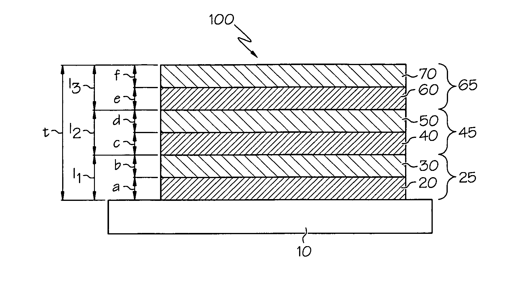
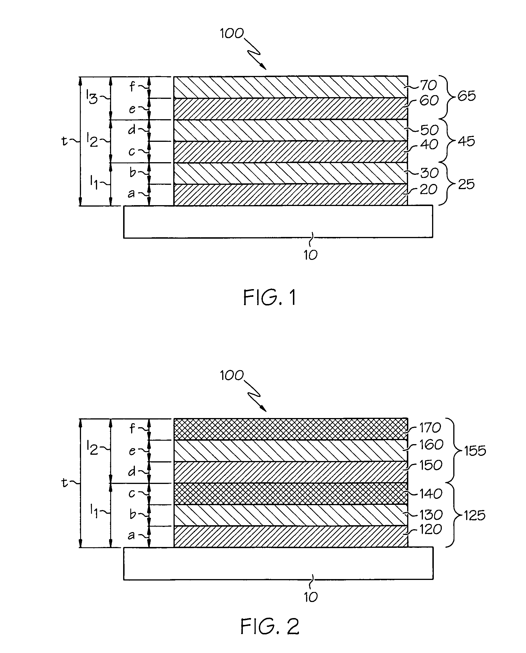
[0053]To examine negative inductance behavior with respect to variation of layer thickness within multilayers, three exemplary inductors were fabricated. The planar conductor structures of the inductors comprised ten multilayers formed by radio-frequency plasma sputtering. Each multilayer comprised a first layer of aluminum and a second layer of copper. The total thickness of the planar conductor structure was approximately 1.0 μm; thus, each multilayer was about 0.1 μm (1000 Å) thick. Each inductor fabricated in this example will be described by the notation AxBy, wherein A is the first metal, B is the second metal, and x and y are thicknesses of the metal layers in each multilayer, normalized to 100. The subscript notation is otherwise unrelated to chemical composition.

[0054]Thus, a first inductor Al34Cu66 was fabricated with all 333 Å thick aluminum layers and 667 Å thick copper layers, for an Al:Cu thickness ratio of 0.5. A second inductor Al50Cu50 was fabricated with all 500 Å ...

example 2

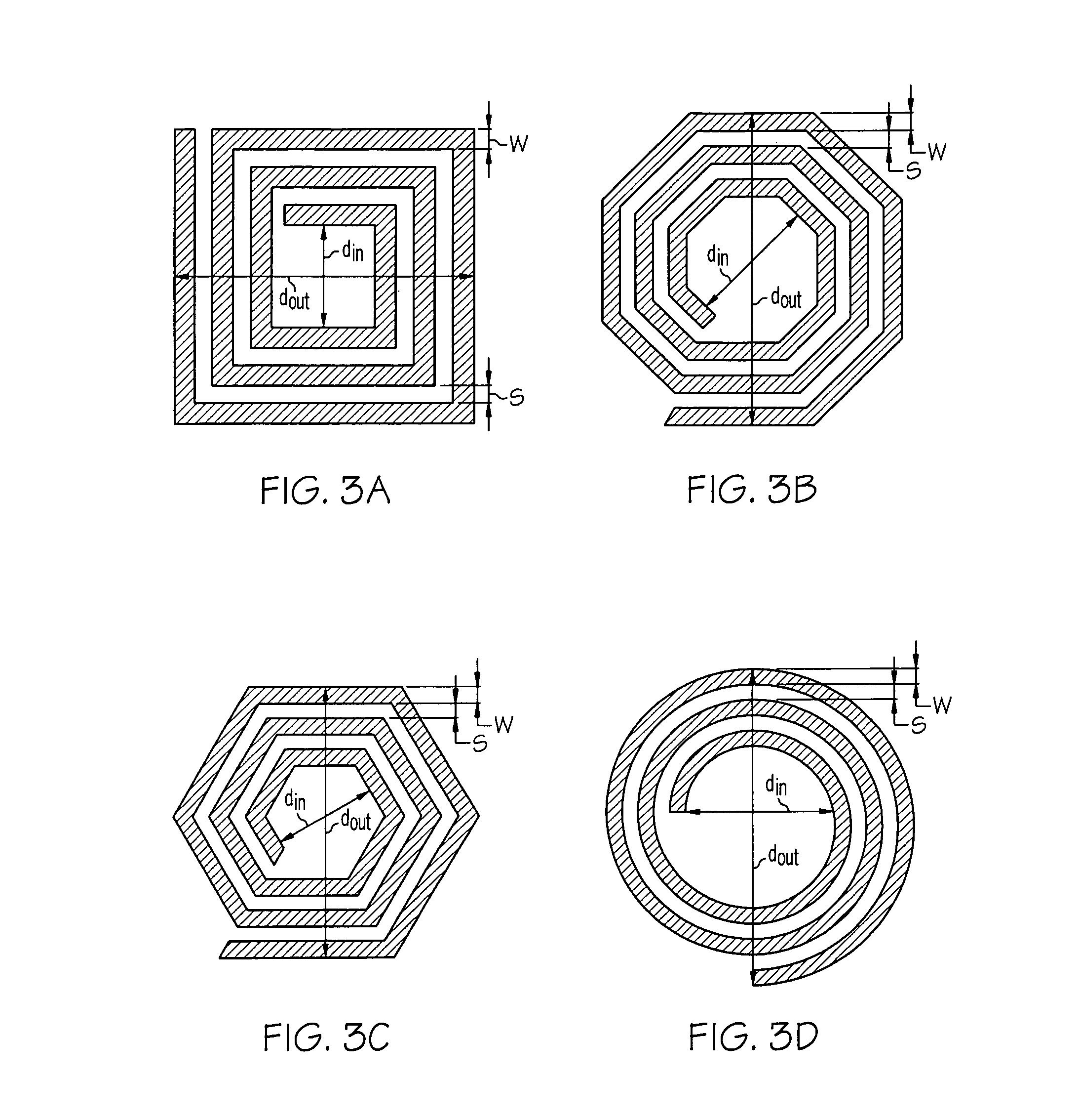
[0056]Additional 10-turn circle inductors were fabricated that showed exceptional negative inductance characteristics below 10 MHz. Each inductor was fabricated with 10 multilayers and planar conductor structure total thickness of 1.0 μm. Described using the thickness notation from Example 1 above, the following thickness ratios resulted in inductors with negative inductance at most frequencies below 10 MHz: Al66Ni34, Al34Ni66, Cu66Ni34, Cu34Ni66, Al66Ag34, and Al16Ni68Cu16.

example 3

[0057]To examine the negative inductance behavior for a given multilayer composition and thickness ratio with respect to number of multilayers, six inductors were fabricated according to embodiments of the present invention. The inductors comprised 2 to 30 Al66Cu34 multilayers, according to the notation described in Example 1 above. The total thickness of each planar conductor was about 1.0 μm. Thus, the thickness of each multilayer varied with respect to number of multilayers, but the thickness ratio of the aluminum layers to the copper layers in each multilayer was constant. The inductance of these inductors with respect to frequency was calculated using the conversion from S-parameters, as described above. The results are compiled in FIG. 7.

[0058]As the data clearly indicate, negative inductance behavior increases in inductors according to embodiments of the invention at all frequencies below 10 MHz as the number of multilayers increases, with total thickness being held constant....


PUM

PropertyMeasurementUnit
total thicknessaaaaaaaaaa
frequencyaaaaaaaaaa
inner radiusaaaaaaaaaa

Abstract

An inductor structure comprising a substrate and a planar conductor structure on a surface of the substrate, and methods for fabricating an inductor structure. The planar conductor structure may comprise a vertical stack of three or more multilayer films. Each multilayer film may comprise a first layer of a first metal, defining a first vertical thickness, and a second layer of a second metal, defining a second vertical thickness. The metals and thicknesses are chosen such that the inductor exhibits a negative electrical self-inductance when an electrical signal is transmitted from a first contact point to a second contact point.

Description

CROSS-REFERENCE TO RELATED APPLICATIONS[0001]This application claims the benefit of the filing date of U.S. Provisional Application Ser. No. 61 / 046,494, filed Apr. 21, 2008.FIELD OF THE INVENTION[0002]The present invention relates generally to passive electronic devices, in particular to thin film structures having negative self-inductance, and to methods for fabricating single, passive components that exhibit negative self-inductance.BACKGROUND OF THE INVENTION[0003]High-speed integrated circuits and semiconductor devices are known to suffer from parasitic inductances that occur, for example, in individual components and around interconnection lines. Inductance is defined generally as the ratio of magnetic flux to electric current. It is well known that when an electrical signal is passed through a conductor, for example, when a variable or periodically alternating current is passed through a wire, a magnetic field is produced around the conductor. The magnetic field varies with re...

Claims


Application Information

Patent Timeline
Patent Type & Authority Patents(United States)
IPC IPC(8): H01F5/00H01F27/28H01L27/08H01F27/02
CPCH01F17/0006H01F2017/0086
Inventor WIDJAJA, AGUSSARANGAN, ANDREW
Owner UNIV OF DAYTON
Learn More