Image display device

a display device and image technology, applied in the field of image display devices, can solve the problems of reducing the image quality of display images, complicating the configuration, and not considering the response characteristic change of a laser diode in correction, and achieve the effect of simple configuration

Inactive Publication Date: 2011-06-14
FUNAI ELECTRIC CO LTD
View PDF13 Cites 17 Cited by
  • Summary
  • Abstract
  • Description
  • Claims
  • Application Information

AI Technical Summary

Benefits of technology

[0014]An object of the present invention is to provide an image display device capable of adjusting the quantity of light in response to output variations of a laser with a simple configuration.
[0024]Accordingly, even if variations in laser output power occur, the output variations are corrected so that the accuracy of laser light output control in the projection region can be enhanced. As a result, even without preparation of a special region for image pattern display for correcting output variations, gradation representation errors of display images caused by laser output variations are reduced, thereby improving the quality of display images with a simplified configuration.
[0025]In addition, since correction of output variations is performed based on the result of comparison with a value indicating the correlation at room temperature of the laser, a change in output power due to a temperature change of the laser itself can be compensated for.

Problems solved by technology

As a result, the quantity of light which should be achieved for a prescribed gradation at room temperature cannot be achieved at a time of a temperature rise, so that the image quality of display images is reduced.
Moreover, special control is required so that an image according to the pattern information is not displayed, thereby complicating the configuration.
However, such a response characteristic change of a laser diode is not considered in correction.

Method used


Image

  • Image display device
  • Image display device
  • Image display device

Examples


Embodiment Construction

[0037]In the following, an embodiment of the present invention will be described with reference to the drawings. In the following description, the same parts are denoted with the same characters. The designations and functions are also the same. Therefore, the detailed description thereof will not be repeated.

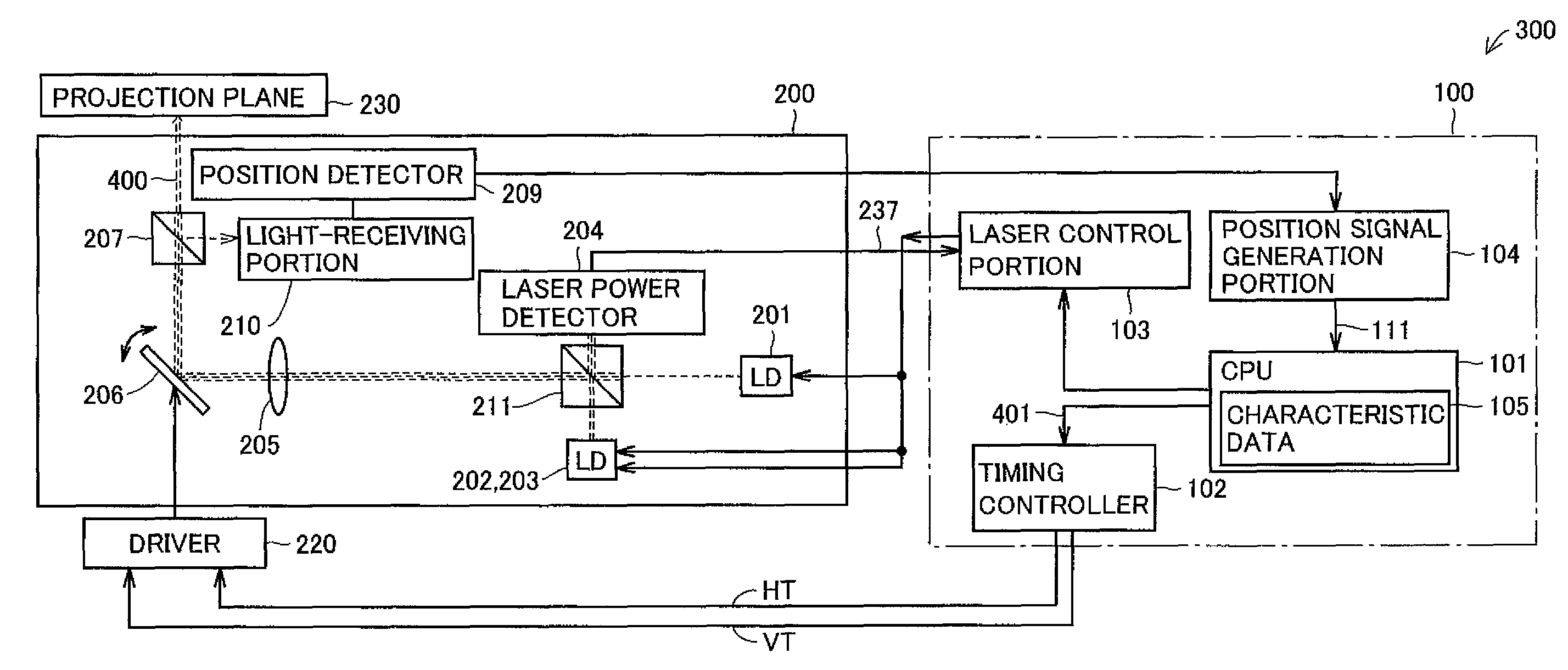
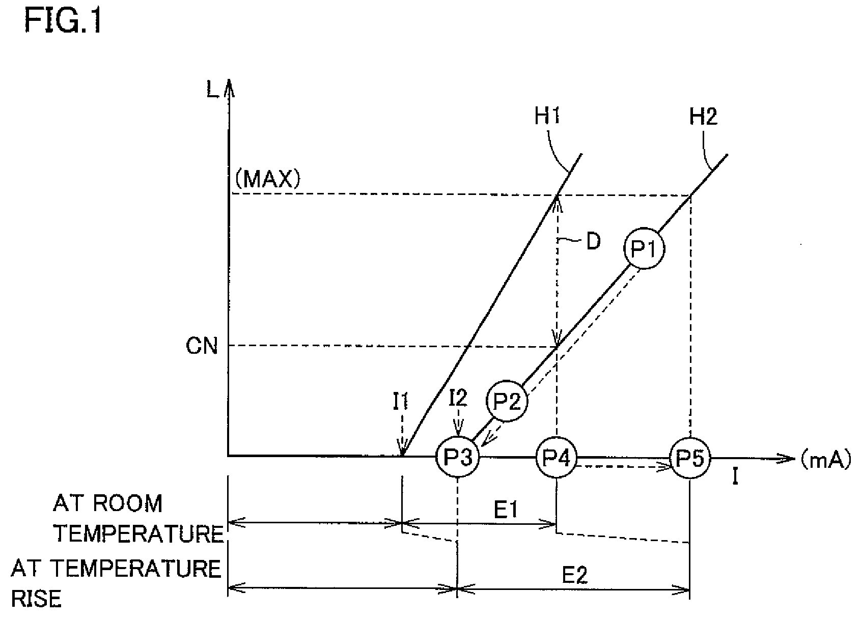
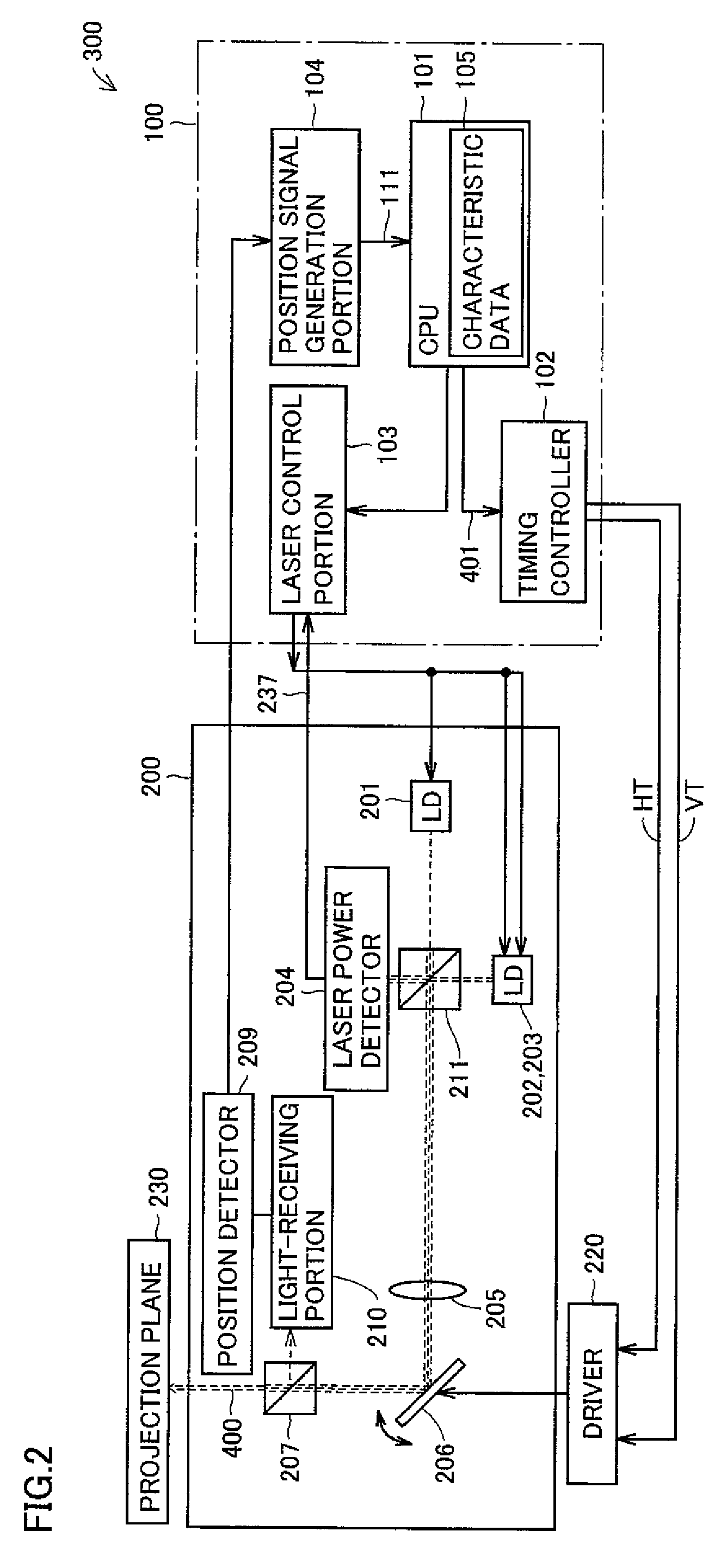
[0038]An image display device in accordance with the present embodiment displays images on projection planes such as screens or walls by scanning images to be displayed with laser light emitted from an LD (Laser Diode) as a light source. For example, the image display device corresponds to a laser projector. LD has such a characteristic in that the luminance of laser light changes with changing temperature of the device. In the image display device, current to be applied to LD (referred to as driving current) is corrected so that the luminance required by the image to be displayed is obtained irrespective of this characteristic. This enables accurate gradation control for the i...


PUM


Abstract

When a position detector detects that the position of a spot on a projection plane designates a non-projection region, the level of a driving signal of a laser is corrected. Specifically, the correlation between the quantity of laser light detected by a light-receiving portion and the level of the driving signal of the laser in accordance with prescribed data is detected. Then, the characteristic value of the laser indicated by the detected correlation is compared with the characteristic value at room temperature stored beforehand to indicate the correlation between the quantity of light emitted by the laser at room temperature and the level of the driving signal. Then, based on the comparison result, the level of the driving signal of the laser in accordance with image data is corrected.

Description

BACKGROUND OF THE INVENTION[0001]1. Field of the Invention[0002]The present invention relates to an image display device, and more particularly to an image display device displaying an image by applying laser light onto a projected plane.[0003]2. Description of the Background Art[0004]Image display devices displaying images by applying laser light onto projected planes such as screens or walls include so-called laser projectors. In a laser projector, laser lights of three primary colors of red, green and blue need to be prepared in order to reproduce images in full color. The configurations concerning image display using laser light in this manner are proposed in the followings.[0005]Japanese Patent Laying-Open No. 2003-005110 discloses an apparatus two-dimensionally scanning light, in which projection of a pattern used for sensing the quantity of light is prevented.[0006]Japanese Patent Laying-Open No. 2007-057555 discloses an image display device capable of displaying high-quality...

Claims


Application Information

Patent Timeline
Patent Type & Authority Patents(United States)
IPC IPC(8): B41J2/435
CPCH04N9/3155H04N9/3129H04N5/7458
Inventor NISHIOKA, KENHIRANO, ATSUYACHIKAOKA, ATSUHIKONISHIGAKI, HIROSHI
Owner FUNAI ELECTRIC CO LTD
Why Eureka
Try Eureka