Fine structure body, process for producing the same, and Raman spectroscopic method and apparatus

a technology of raman and structure, applied in the direction of optical radiation measurement, instruments, spectrometry/spectrophotometry/monochromators, etc., can solve the problems of not always being able to detect raman scattered light, and not always being able to produce devices with high reproducibility. , to achieve the effect of enhancing raman scattered light, high quality and high performan

Inactive Publication Date: 2011-06-28
FUJIFILM CORP
View PDF6 Cites 0 Cited by
  • Summary
  • Abstract
  • Description
  • Claims
  • Application Information

AI Technical Summary

Benefits of technology

[0014]The primary object of the present invention is to provide a fine structure body, which is provided with a function of enhancing Raman scattered light, and which has high performance and high quality.
[0015]Another object of the present invention is to provide a process for easily and reliably producing a fine structure body, which is provided with a function of enhancing Raman scattered light, and which has high performance and high quality.

Problems solved by technology

Therefore, ordinarily, it is not always possible to detect the Raman scattered light.
However, with each of the disclosed processes described above, the problems are encountered in that the number of processing steps is not capable of being kept small.
Also, with each of the disclosed processes described above, the problems are encountered in that, in order for regularity of the fine holes formed by the anodic oxidation processing to be enhanced, it is necessary for Cr to be added.
Further, with each of the disclosed processes described above, the problems are encountered in that, since precise condition setting is required for the production of the device, it is not always possible to produce the device with a high reproducibility.
However, in cases where the spherical gold nanoparticles are utilized, it is necessary for the size of each of the gold nanoparticles to be set to be large, and the quantity of gold used becomes large.
Therefore, in such cases, the cost is not capable of being kept low.
Also, in the cases of the spherical particles, the area of the region, in which the adjacent particles are closest to each other, is small, and therefore a high degree of the enhancement is not capable of being obtained.
However, with the alternating adsorption technique, the metal nanorods are not capable of being fixed at a high density.
Also, with the alternating adsorption technique, the distance between the metal nanorods and the orientation of the metal nanorods are not capable of being controlled.
Therefore, it is not always possible to achieve sufficient enhancement of the intensity of the Raman scattered light and reproducible production of the device.
However, with the technique, in which the gold nanorods are aggregated at the water phase-oil phase interface, the spacing between the gold nanorods is not capable of being controlled, and the gold nanorods are not capable of being distributed and located without defects on the surface of the base plate.
Therefore, it is not always possible to achieve sufficient enhancement of the intensity of the Raman scattered light and reproducible production of the device.
Also, the technique described above, in which an organic solvent is utilized, is not appropriate from the view point of environmental protection.

Method used


Image

  • Fine structure body, process for producing the same, and Raman spectroscopic method and apparatus
  • Fine structure body, process for producing the same, and Raman spectroscopic method and apparatus
  • Fine structure body, process for producing the same, and Raman spectroscopic method and apparatus

Examples


example 1

Production of the Fine Structure Body

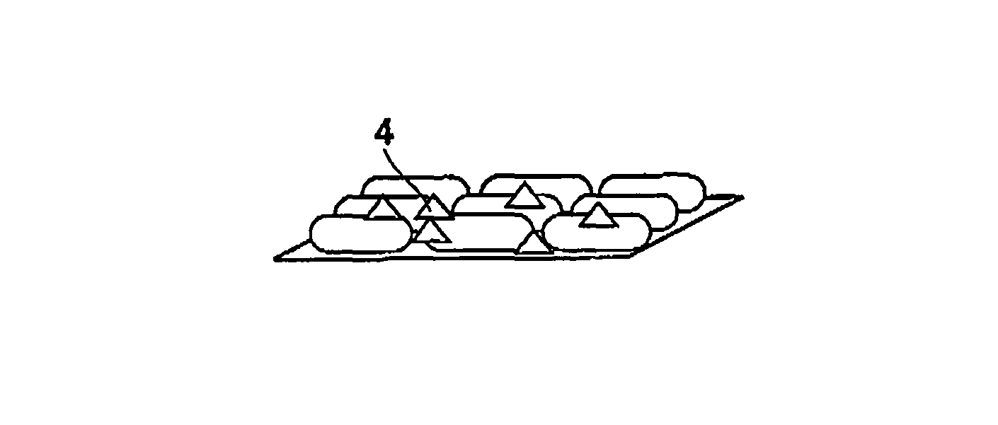
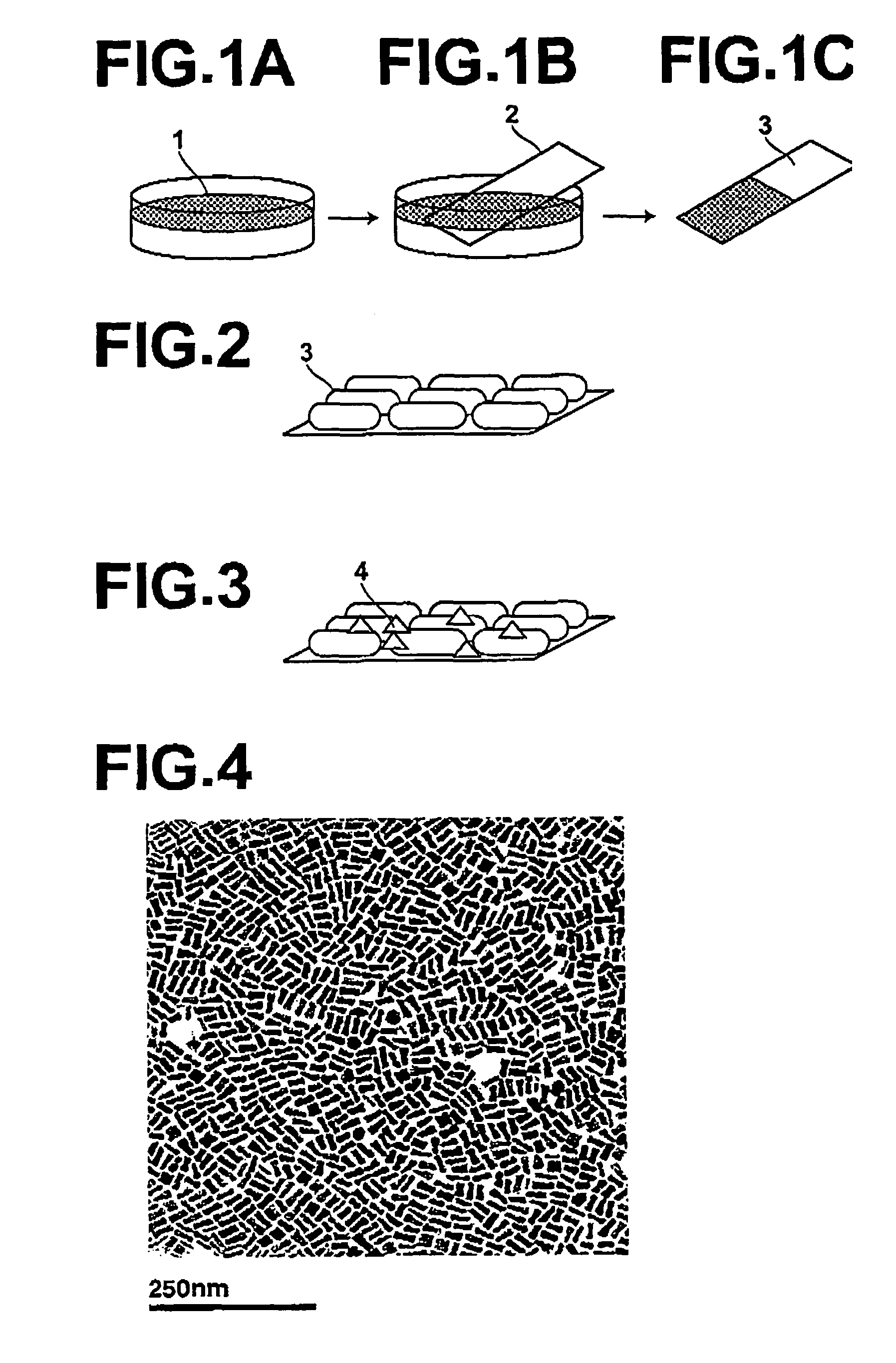
[0079]The device (acting as the fine structure body) 3, which comprised the base plate 2 and the gold nanorod thin film 1 having been fixed to the base plate 2, was produced in accordance with the procedure illustrated in FIGS. 1A, 1B, and 1C. Specifically, firstly, deionized water was introduced into a glass laboratory dish having an inside diameter of 7.0 cm. Thereafter, 30 μl of a gold nanorod dispersion, which contained gold nanorods having a minor axis length of approximately 13 nm and a major axis length of approximately 45 nm in chloroform, and which had been adjusted at a gold solid concentration of 1 wt %, was added little by little onto the surface of the deionized water. From the result of a calculation made in accordance with the size of the gold nanorods, it was found that approximately 6.6×10¹² pieces of the gold nanorods would be capable of being located so as to stand side by side on the surface of the deionized water contained in...

example 2

Raman Scattering Measurement

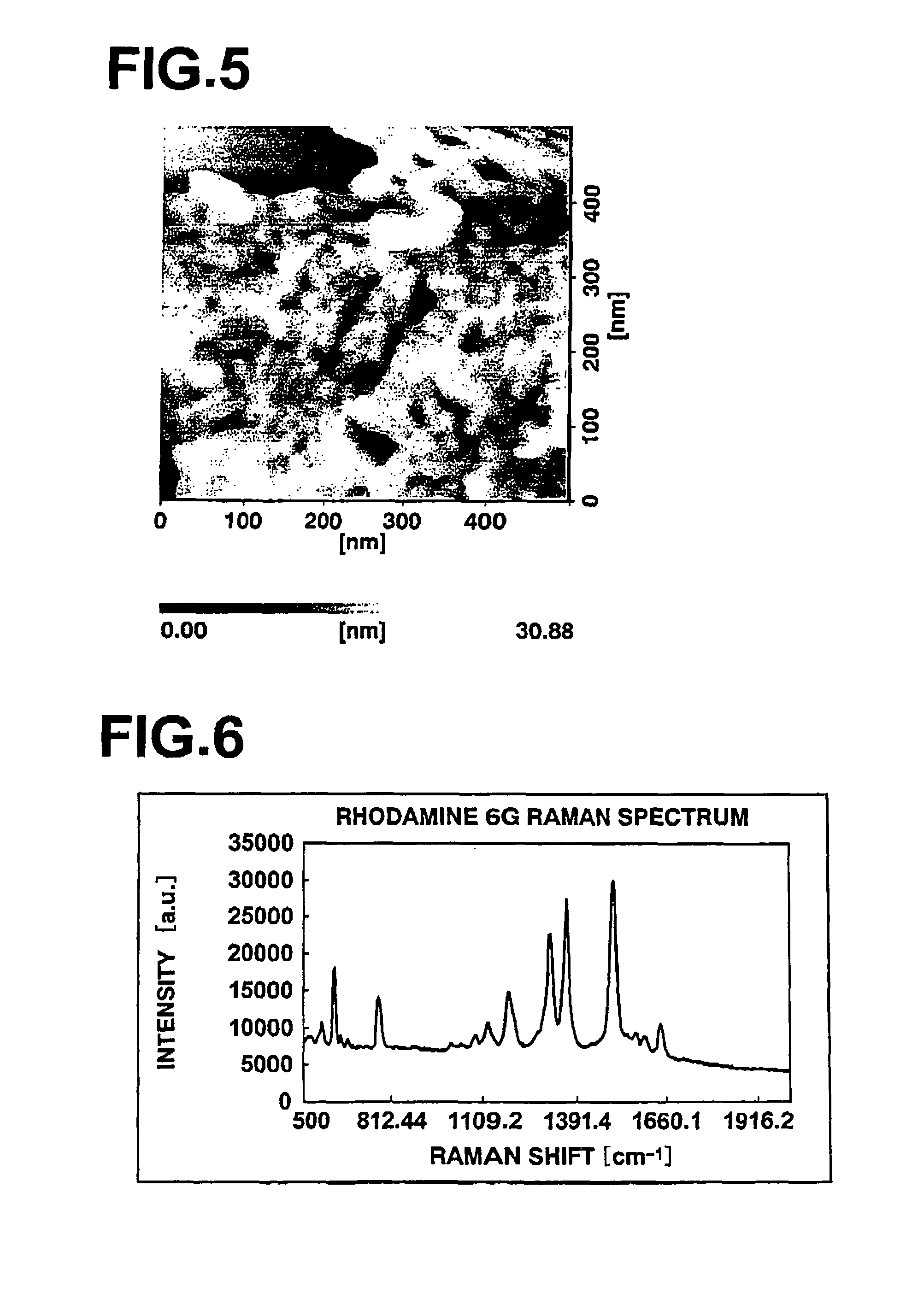
[0080]As for each of the device A, the device B, and the device C having been produced in Example 1, the Raman scattering measurement was made in the manner described below. Specifically, as the substance to be analyzed, a 260 μmol / l ethanol solution of Rhodamine 6G was used. As for each of the device A, the device B, and the device C, 10 μl of the aforesaid ethanol solution was added little by little onto the fine structure body surface having an area of 1.4×1.7 cm2. After ethanol was removed by evaporation, a Raman spectrum was measured. As the Raman measuring apparatus, LabRAM HR-800 (supplied by Horiba Co.) was used. The exciting laser beam wavelength was 785 nm, and the laser power was 30 mW. Since Rhodamine 6G did not exhibit absorption in the near infrared wavelength region, the effect of the resonance Raman scattering did not occur.

[0081]FIG. 6 is a graph showing a Raman scattering spectrum obtained with the device A, to which Rhodamine 6G has bee...


PUM

PropertyMeasurementUnit
lengthaaaaaaaaaa
lengthaaaaaaaaaa
near infrared wavelengthaaaaaaaaaa

Abstract

A fine structure body comprises: (i) a base body, and (ii) a plurality of metal nanorods, which have been distributed and located on a surface of the base body, a proportion X being equal to at least 15%, the proportion X being calculated with the formula:X=(A−B) / C×100[%]wherein A represents the sum total of the projected areas of all of the metal nanorods, B represents the sum total of the projected areas of certain metal nanorods, each of which is located as an isolated metal nanorod at a spacing larger than 10 nm from the closest metal nanorod, and C represents the entire projected area of the fine structure body, including regions free from the metal nanorods.

Description

BACKGROUND OF THE INVENTION[0001]1. Field of the Invention[0002]This invention relates to a fine structure body adapted to utilization for Raman spectroscopy. This invention also relates to a process for producing the fine structure body. This invention further relates to a Raman spectroscopic method and apparatus utilizing the fine structure body.[0003]2. Description of the Related Art[0004]Raman spectroscopy is a technique, wherein scattered light, which is obtained from irradiation of light having a single wavelength to a sample substance, is separated into spectral components of the scattered light, wherein a spectrum (hereinbelow referred to as the Raman spectrum) is thereby obtained, and wherein light (hereinbelow referred to as the Raman scattered light) having wavelengths different from the wavelength of the incident light is detected in accordance with the Raman spectrum. The Raman scattered light has a markedly low intensity. Therefore, ordinarily, it is not always possibl...

Claims


Application Information

Patent Timeline
Patent Type & Authority Patents(United States)
IPC IPC(8): C30B29/62
CPCB82Y15/00G01J3/44G01N21/658B22F2998/00Y10T117/1008B22F1/0025B22F1/0547
Inventor MATSUNAMI, YUKI
Owner FUJIFILM CORP
Why Eureka
Try Eureka