Method for estimating relative clock frequency offsets to improve radio ranging errors

a technology of relative clock frequency offset and radio ranging error, applied in direction finders, directions using radio waves, instruments, etc., can solve problems such as 20 ns time error, acfo and/or rcfo introduce errors, and achieve the effect of minimizing range estimation errors

Inactive Publication Date: 2011-06-28
MITSUBISHI ELECTRIC RES LAB INC
View PDF6 Cites 7 Cited by
  • Summary
  • Abstract
  • Description
  • Claims
  • Application Information

AI Technical Summary

Benefits of technology

[0032]The invention provides a method for estimating a relative clock frequency offset (RCFO) between two wireless communication devices with asynchronous clocks by performing a data packet exchange. The method minimizes range estimation error in a two-way time-of-arrival (TOA) measurements.

Problems solved by technology

The CFO and RCFO can cause problem.
When the clock is used for time measurement, the ACFO and / or RCFO introduce errors.
In the example, fnorm=100 MHz, t=999,980 ns, which results in a 20 ns time error.
If the same time period is measured by two devices using independent clocks, the RCFO causes a discrepancy in the measurements.
Because the turnaround time at the second device is much larger than the signal ‘flying’ time, the error caused by RCFO is the dominant factor in the overall time estimation error for a TW-TOA system.
However, in practice, the desired improvements may not be feasible.
ΔfXY / f is determined by the components performance (in particular, the crystal oscillator) and a higher accuracy / stability components are more costly and may require more complicated circuit design.
The process time, t12 is often determined by several factors and cannot be easily reduced because many communication standards impose a quite period between transmissions, and the receiving device must process the data and pass the packet to the upper layer and the processing time is long, and the length of the payload portion of the packet is often non-zero.
Such a method does not yield an accurate RCFO estimation because the preamble has a finite duration.
Therefore, the time interval between two symbols cannot be very large, the method does not benefit from the processing gain by using as many symbols in the preamble, and the method is sensitive to carrier frequency offset and sample timing errors.
The drawbacks of such a method are: the times treplyA and treplyB must be identical or very close in order to cancel out the error caused by the RCFO; additional transmissions are needed to pass the information from one device to the other device; and delay mismatches in RF frond ends of two devices may introduce additional errors.
This approach requires the storage of a large number of samples, a complex FFT operation and therefore requires additional hardware, software and power.

Method used


Image

  • Method for estimating relative clock frequency offsets to improve radio ranging errors
  • Method for estimating relative clock frequency offsets to improve radio ranging errors
  • Method for estimating relative clock frequency offsets to improve radio ranging errors

Examples


Embodiment Construction

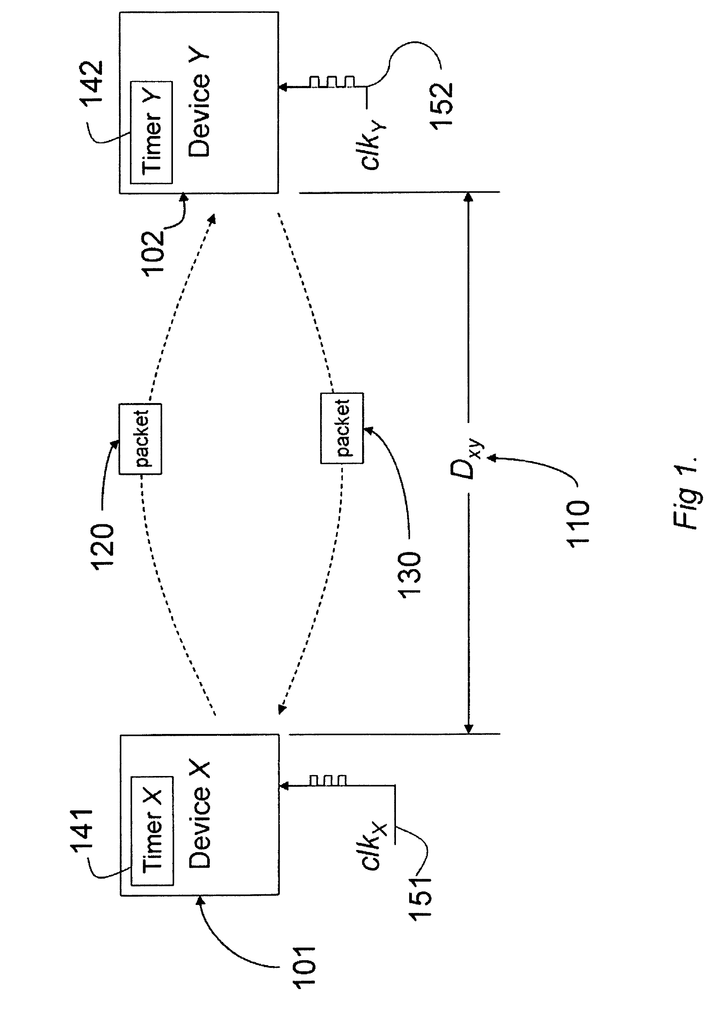
[0039]Wireless Ranging Devices

[0040]FIG. 1 shows wireless communication device X 101 and device Y 102 according to an embodiment of the invention. A distance between device X and device Y is DXY 110. Device X can transmit a data packet 120 to device Y, and device Y can transmit a data packet 130 to device Y. FIG. 1 also shows timer X 141 and timer Y 142, and clock signals clkX 151 and clkY 152. The timers count the clock signals. The timers are identical other than that count clock signals having different frequencies due to offsets from their nominal (design) frequency. A device may have multiple timers.
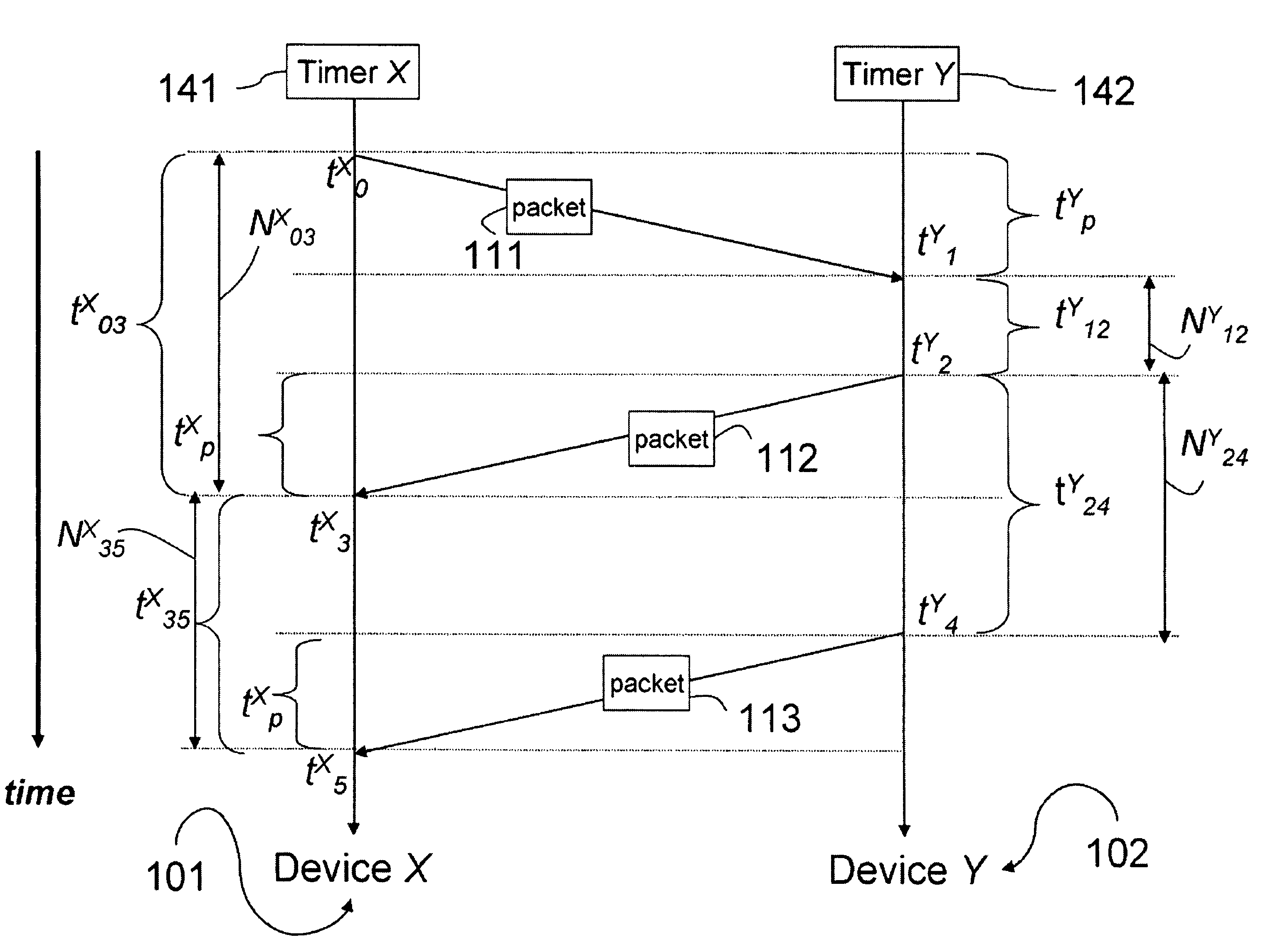
[0041]Timers

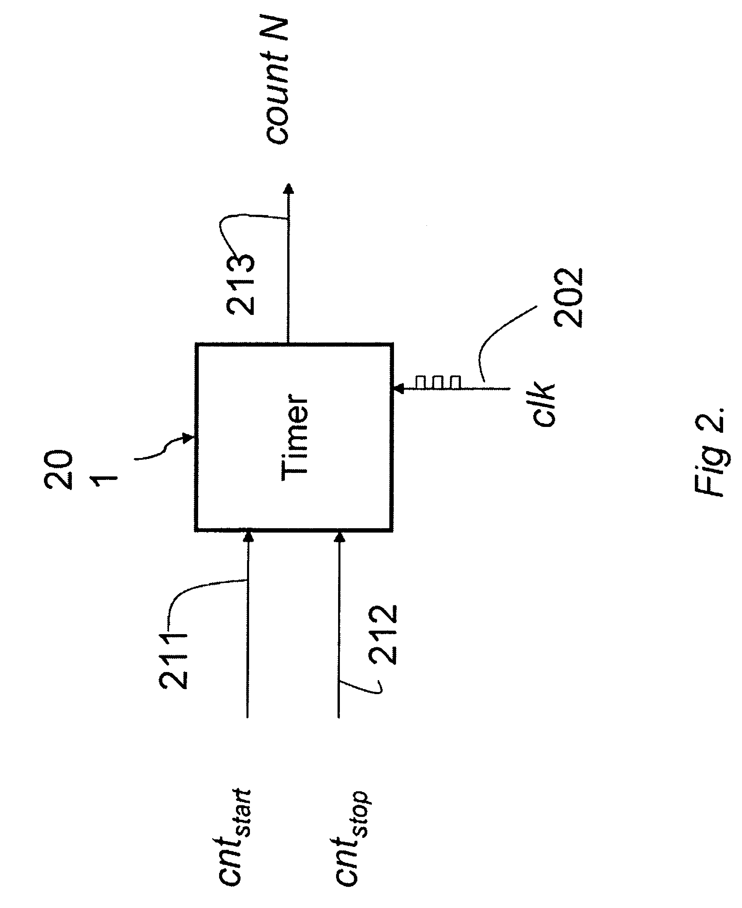
[0042]FIG. 2 generally shows a timer 201 operated according to a signal clk 202 having a nominal clock frequency fnorm. Of course, the nominal frequency is known at both devices. The time 201 forms the basis for timers 141-142.

[0043]The timer starts counting when a signal cntstart 211 is active (ON), and stops counting when cntstop 212 is active. The timer outputs a coun...


PUM


Abstract

A method and system improves two-way radio ranging accuracy by estimating a relative clock frequency offset between a first clock X of a first transceiver and a second clock Y a second transceiver. The first transceiver transmits a first packet at time t0 received by the second transceiver at a time t1. The second transceiver transmits a second packet at a time t2 received by first transceiver at a time t3. The second transceiver transmits a third packet at a time t4 received at a time t5. The relative clock frequency offset is thenΔ⁢⁢fXY′≅2⁢⁢f⁡(N24Y-N35X)N24Y+N35X,where f is a nominal clock frequency of the first and second clocks, NY24 is a measured first delay between times t2 and t4 of the second clock, NX35 is a measured second delay between times t3 and t5 of the first clock X.

Description

FIELD OF THE INVENTION[0001]This invention relates to wireless communication systems, and more particularly, to accurate ranging estimation through relative clock frequency offsets (RCFO) compensation between wireless devices.BACKGROUND OF THE INVENTION[0002]In many wireless communication networks, devices are not synchronized to a single reference clock. Instead, each device relies on its own clock. Due to the limitation of the hardware, manufacturing processes, temperature drift, component aging, etc., the actual operating frequency of the clock is generally different from the designed nominal frequency. For example, if a 100 MHz clock signal is generated by a crystal that has a tolerance of + / −20 parts per million (ppm), the actual frequency of the clock can be any value in a range from 99,998,000 Hz to 100,002,000 Hz.[0003]A difference between the actual frequency of the clock and the designed nominal frequency is referred to as the ‘clock frequency offset’ (CFO) or ‘absolute cl...

Claims


Application Information

Patent Timeline
Patent Type & Authority Patents(United States)
IPC IPC(8): H04J3/06G01S3/02
CPCG01S13/765
Inventor DUAN, CHUNJIEVANNUCCI, GIOVANNI
Owner MITSUBISHI ELECTRIC RES LAB INC
Why Eureka
Try Eureka