Insert adapted for use in bar peeling and method

a technology for inserts and peeling bars, which is applied in the direction of cutting inserts, manufacturing tools, shaping cutters, etc., can solve the problems of reducing the service life of peeling inserts and increasing the electric power consumption of peeling machines, so as to avoid chatter marks, increase cutting performance, and increase the service life of cutting edges

Inactive Publication Date: 2011-07-05
BOEHLERIT GMBH & CO KG
View PDF22 Cites 5 Cited by
  • Summary
  • Abstract
  • Description
  • Claims
  • Application Information

AI Technical Summary

Benefits of technology

[0010]The invention aims to eliminate these disadvantages and provides for an insert of the type mentioned at the outset, which renders possible bar peeling with a smooth machine action or with a smooth cutting having low electric power consumption, avoids chatter marks on the rod, and provides increased service life of the cutting edges along with increased cutting performance.

Problems solved by technology

The electric power consumption of the peeling machine is also thereby increased and the service life of the peeling inserts seems reduced.

Method used


Image

  • Insert adapted for use in bar peeling and method
  • Insert adapted for use in bar peeling and method

Examples


Embodiment Construction

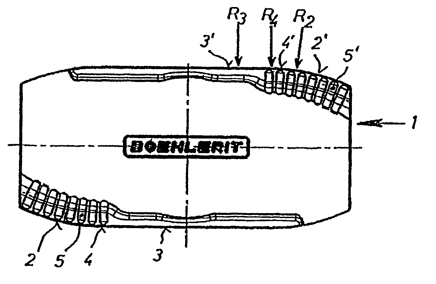
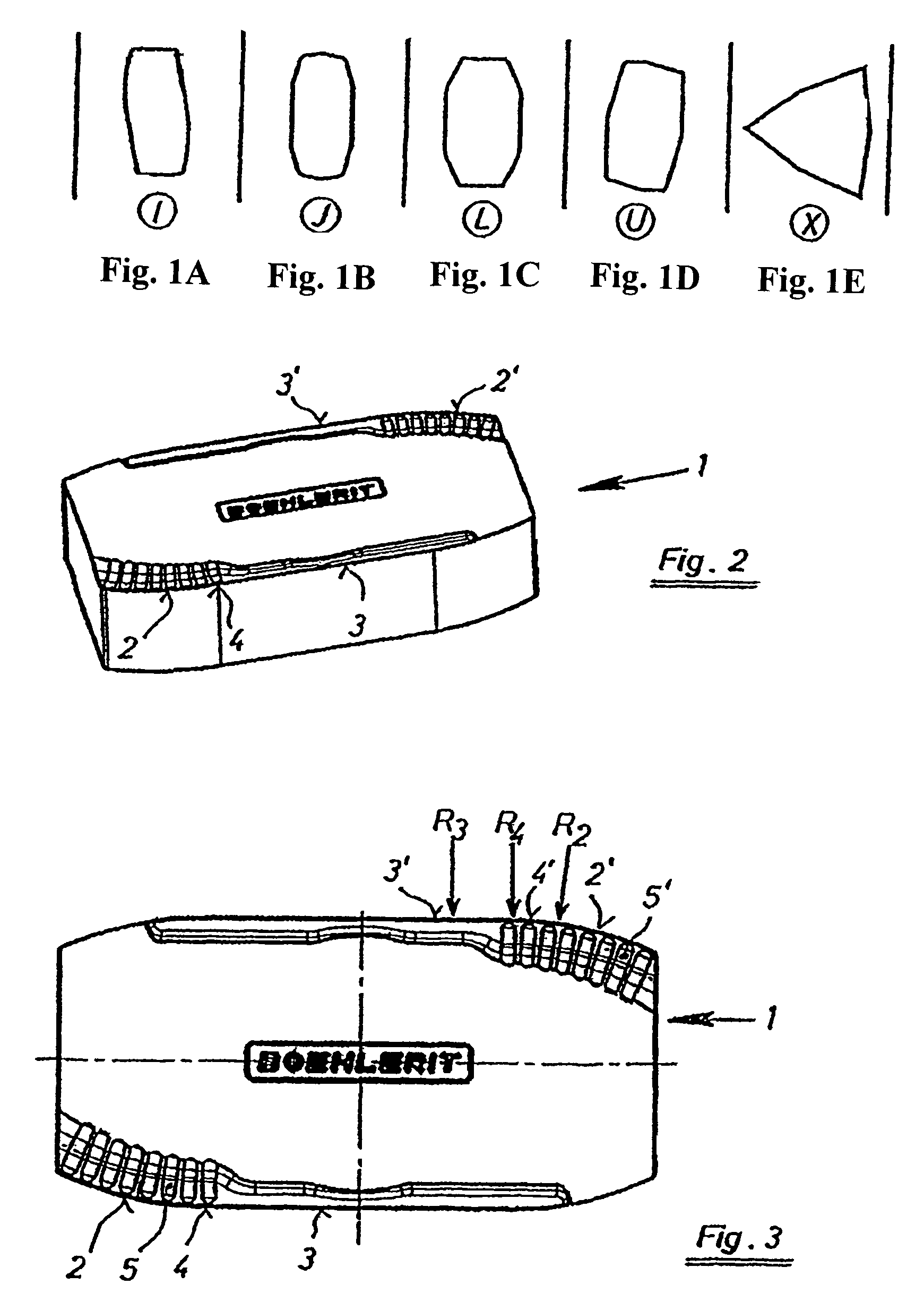
[0030]In FIGS. 1A-1E, different prior art polygonal indexable inserts for bar peeling operations are shown diagrammatically in plan view, and are labeled in each case. That is, the different insert shapes are labeled “I”, “J”, “L”, “U” and “X”. Each of the inserts according to the prior art has at least one primary cutting edge and at least one secondary or smoothing cutting edge for a chip removal. These cutting edges form an obtuse angle with one another. An installation of indexable inserts is thereby carried out in cassettes of a cutting head, such that a secondary or smoothing cutting edge respectively of an insert is aligned essentially parallel to the axis of a billet to be peeled, or a rotational axis of a peeling tool, and a primary cutting edge runs at an obtuse angle outwards against a feed direction of the billet.

[0031]No specific polygonal form of an indexable insert is necessary for a geometry of the cutting edges according to the invention. Instead, the only essential...


PUM

PropertyMeasurementUnit
lengthaaaaaaaaaa
lengthaaaaaaaaaa
radiusaaaaaaaaaa

Abstract

An insert for rotary milling includes a polygonal member having at least one primary cutting edge and at least one secondary cutting edge arranged at an obtuse angle thereto. At least one connecting region is arranged between the at least one primary cutting edge and the at least one secondary cutting edge. The connecting region has a local radius of curvature. This abstract is not intended to define the invention disclosed in the specification, nor intended to limit the scope of the invention in any way.

Description

CROSS-REFERENCE TO RELATED APPLICATIONS[0001]The present application is a U.S. National Stage of International Patent Application No. PCT / AT2006 / 000104 filed Mar. 13, 2006 which published as WO 2006 / 099640 on Sep. 28, 2006, and claims priority of Austrian Patent Application No. A 513 / 2005 filed Mar. 24, 2005.BACKGROUND OF THE INVENTION[0002]1. Field of the Invention[0003]The invention relates to an insert for bar peeling operations wherein the insert has a polygonal form in plan view as well as at least one primary cutting edge and one secondary cutting edge arranged at an obtuse angle thereto. The insert can also be reversible.[0004]2. Discussion of Background Information[0005]Semi-finished products, e.g., of stainless steel or of highly-alloyed materials, are generally produced by hot working the raw material. Before the semi-finished product is processed further, it can be necessary to machine the surface thereof. This machining is utilized in order to eliminate deformation troug...

Claims


Application Information

Patent Timeline
Patent Type & Authority Patents(United States)
IPC IPC(8): B23B27/22B23P15/28
CPCB23B5/12B23B27/141B23B2200/087B23B2200/123Y10T407/235B23B2200/202B23B2220/40Y10T407/23Y10T407/245B23B2200/201
Inventor BAERNTHALER, WALTERTRINK, HELMUT
Owner BOEHLERIT GMBH & CO KG
Why Eureka
Try Eureka