Turbine anti-rotating stall schedule

a turbine and rotating stall technology, applied in the direction of turbine/propulsion engine ignition, engine starter, liquid fuel engine, etc., can solve the problems of rotating stall, limited variable stage geometry of turbines, limited air extraction, etc., and achieve the effect of increasing the speed of blade rotation

Active Publication Date: 2011-07-05
GE INFRASTRUCTURE TECH INT LLC
View PDF5 Cites 39 Cited by
  • Summary
  • Abstract
  • Description
  • Claims
  • Application Information

AI Technical Summary

Benefits of technology

[0006]The present application thus provides a method of starting up a turbine with a compressor have an inlet guide vane, a number of bleed valves, and a number of blades so as to limit the duration in a rotating stall window. The method may include starting rotation of the blades, increasing the speed of the rotation of the blades, closing one or more bleed valves so as to shift the rotating stall window to a higher rotational speed, partially opening the inlet guide vane to a position outside the rotating stall window, and opening the bleed valves while partially closing the inlet guide vane such that the number of blades pass through the rotating stall window.
[0009]The application further describes a method of starting up a turbine with a compressor have an inlet guide vane, a number of bleed valves, and a number of blades so as to limit the duration in a rotating stall window. The method may include starting rotation of the number of blades, increasing the speed of the rotation of the blades, closing one or more bleed valves so as to shift the rotating stall window to a higher rotational speed, and modulating the inlet guide vane such that the blades pass through the rotating stall window.

Problems solved by technology

Such turbines have limited variable stage geometry and limited air extractions.
As a result, gas turbines often have significant off design aerodynamic conditions during start-up and shutdown operations.
These conditions can result in rotating stall.
The cells provide a coherent pressure wave that may align with the natural frequencies of the blades and may result in resonance.
Such vibratory resonance on the rotor and stator blades may lead to increase sensitivity to normal blade damage and therefore may result in premature failures.
Rotating stall induced stresses also may be high enough to initiate a crack on a blade.
Such cracks inevitably will propagate and lead to blade failure.
Significant compressor damage also may occur as well as un-scheduled turbine downtime, repair costs, and reduce customer satisfaction.

Method used


Image

  • Turbine anti-rotating stall schedule
  • Turbine anti-rotating stall schedule
  • Turbine anti-rotating stall schedule

Examples


Embodiment Construction

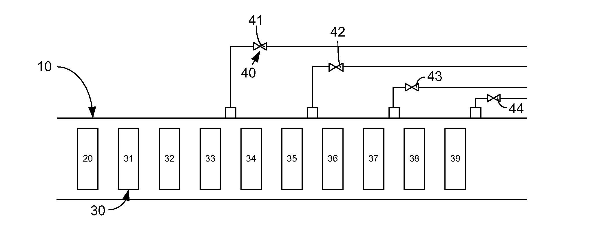
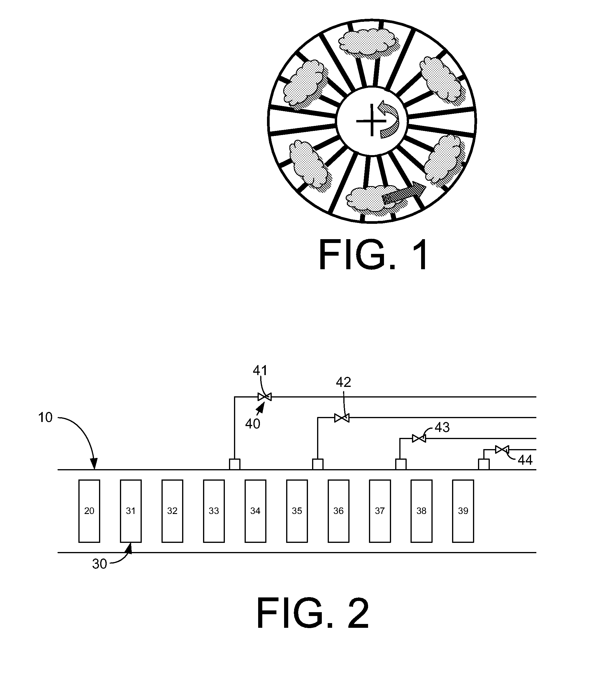
[0016]Referring now to the drawings, in which like numerals refer to like elements throughout the several views, FIG. 2 is a schematic view of a compressor 10. The compressor 10 includes an inlet guide vane (“IGV”) 20 at an inlet end. The compressor 10 then has a variable number of rotor and stator blades 30. In this example, nine pairs of blades, 31, 32, 33, 34, 35, 36, 37, 38, 39 are shown. Any number of blades 30 may be used herein. A number of bleed valves 40 may be positioned about the blades 30. In this example, four bleed valves, 41, 42, 43, 44 are shown. Any number of bleed valves 40 may be used. In this example, the bleed valves 40 are positioned after the third pair 33, the fifth pair 35, the seventh pair 37, and the ninth pair 39. Other positions and other compressor configurations may be used herein.

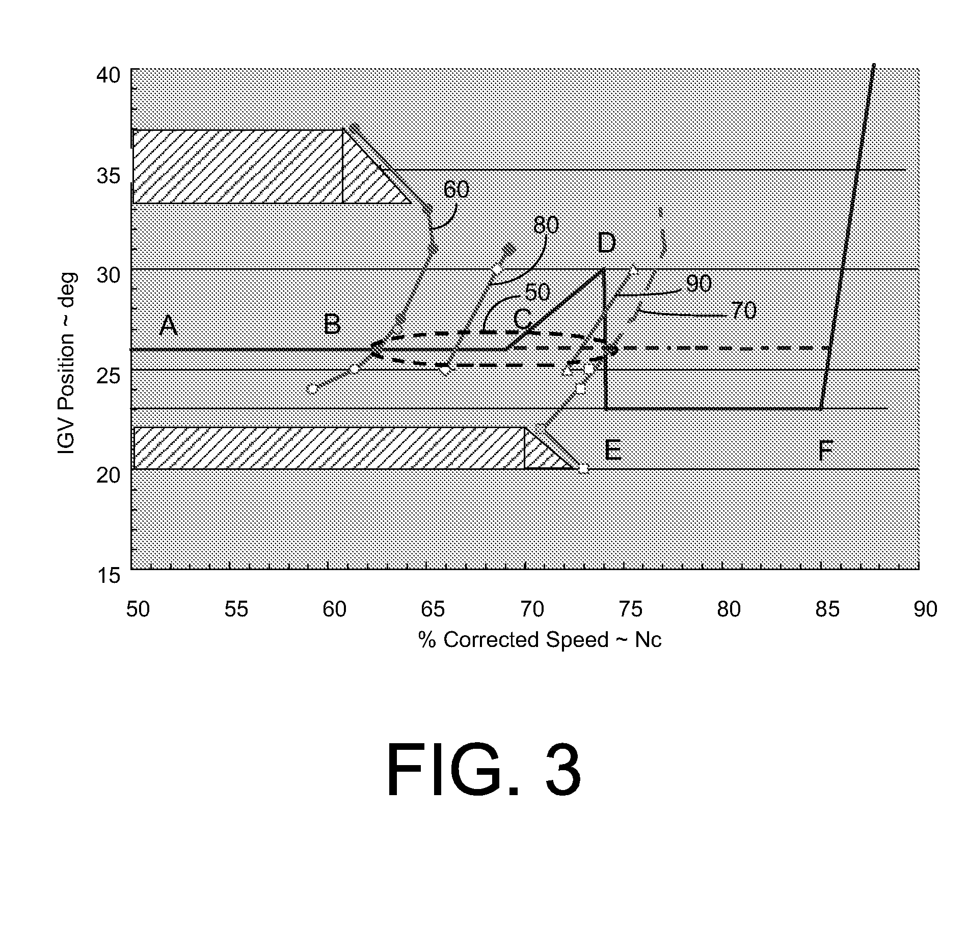
[0017]Referring now to FIG. 3, the current control logic is shown in part as a dotted line. In this example, the inlet guide vane 20 is held at about a constant 26 degrees un...


PUM


Abstract

A method of starting up a turbine with a compressor have an inlet guide vane, a number of bleed valves, and a number of blades so as to limit the duration in a rotating stall window. The method may include starting rotation of the blades, increasing the speed of the rotation of the blades, closing one or more bleed valves so as to shift the rotating stall window to a higher rotational speed, partially opening the inlet guide vane to a position outside the rotating stall window, and opening the bleed valves while partially closing the inlet guide vane such that the number of blades pass through the rotating stall window.

Description

TECHNICAL FIELD[0001]The present application relates generally to gas turbines and more particularly relates to turbine start-up and shutdown schedules that prevent rotating stall.BACKGROUND OF THE INVENTION[0002]Gas turbines are designed generally to operate within a specific rotational speed and output range. Such turbines have limited variable stage geometry and limited air extractions. As a result, gas turbines often have significant off design aerodynamic conditions during start-up and shutdown operations. These conditions can result in rotating stall.[0003]Rotating stall, as is shown schematically in FIG. 1, generally involves a number of local stall cells that may rotate at about half the rotor speed. The stall cells may provide coherent unsteady aerodynamic loads on both the rotor and the stator blades. The number and shape of the cells set up different orders of excitation or nodal diameters. The cells provide a coherent pressure wave that may align with the natural frequen...

Claims


Application Information

Patent Timeline
Patent Type & Authority Patents(United States)
IPC IPC(8): F01D17/16F01D17/00F01D19/00F01D21/00
CPCF01D19/00F02C6/08F02C9/22F04D27/0207F04D27/0284F02C9/18F04D27/0223F04D27/023F04D27/0246F04D29/522F02C7/26
Inventor DEJORIS, TIMOTHYDUTKA, MICHAEL J.MARTIN, NICKSCHIRLE, STEVEN M.
Owner GE INFRASTRUCTURE TECH INT LLC
Why Eureka
Try Eureka