Power supply system employing conductive fluid

a technology of conductive fluid and power supply system, which is applied in the direction of positive displacement liquid engine, machine/engine, electric generator control, etc., can solve the problems of affecting the reliability of the lsi, generating heat that cannot be dissipated by the heat sink, and chip malfunction or long-term reliability degradation, etc., to achieve the effect of cooling a semiconductor integrated circui

Active Publication Date: 2011-07-05
SONY COMPUTER ENTERTAINMENT INC
View PDF16 Cites 17 Cited by
  • Summary
  • Abstract
  • Description
  • Claims
  • Application Information

AI Technical Summary

Benefits of technology

[0005]The present invention was developed in view of these problems. It is therefore an object of the invention to provide a power supply system which is capable of effectively cooling a semiconductor integrated circuit and supplying power thereto at the same time.

Problems solved by technology

At high temperatures, the chip will malfunction or suffer from degradation in long-term reliability.
Recent LSIs, particularly high-performance microprocessors, may generate heat that cannot be dissipated by the heat sink.
It is thus an everlasting challenge to improve the efficiency of heat dissipation.
Additionally, there is also a problem that the density of an electric current flowing through a terminal of an LSI connected to a circuit board or the like may have an adverse effect on the reliability of the LSI because the terminal has a limited current capacity.
Thus, the power supply to the LSI is also recognized as a critical technical issue.

Method used


Image

  • Power supply system employing conductive fluid
  • Power supply system employing conductive fluid
  • Power supply system employing conductive fluid

Examples


Embodiment Construction

[0018]The invention will now be described based on preferred embodiments which are not intended to limit the scope of the present invention, but rather exemplify the invention. All of the features and the combinations thereof described in the embodiment are not necessarily essential to the invention.

[0019]Now, the present invention will be described below first in outline and then in more detail with reference to the accompanying drawings in accordance with the embodiments.

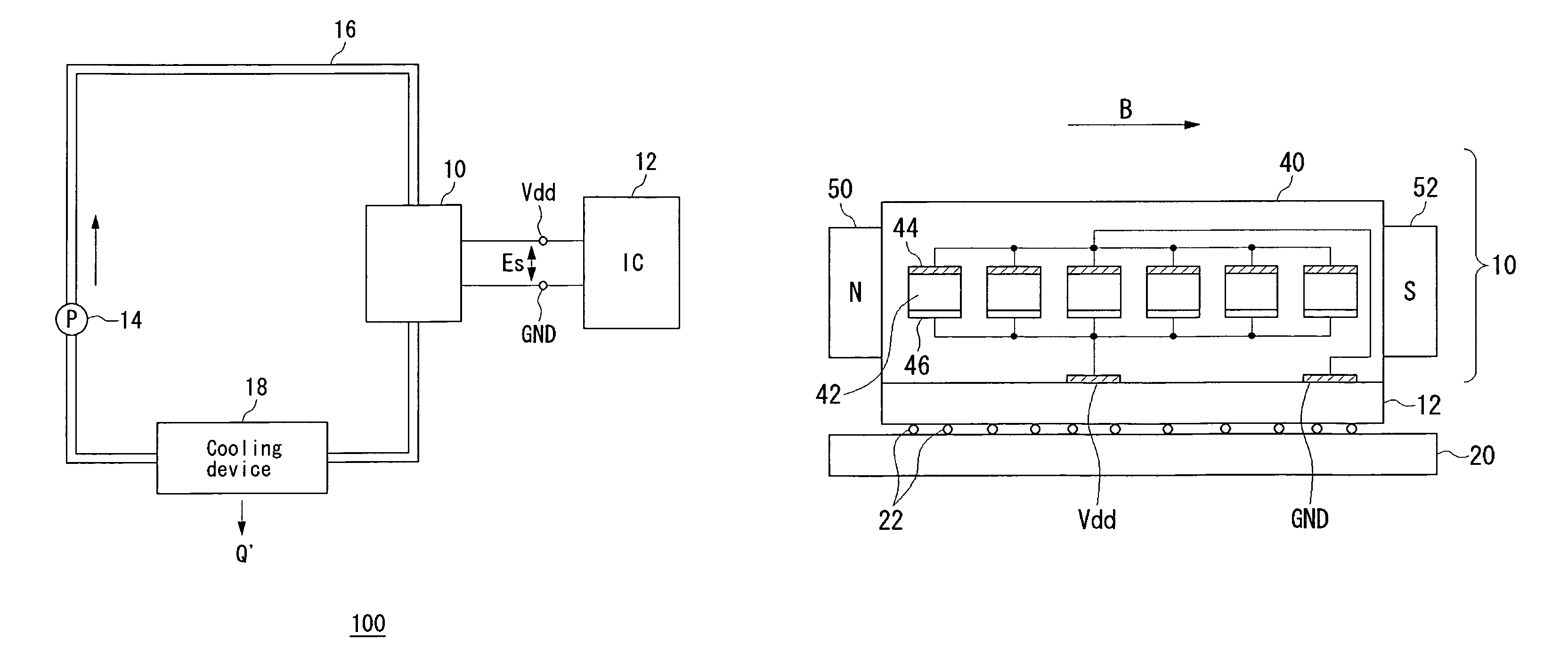
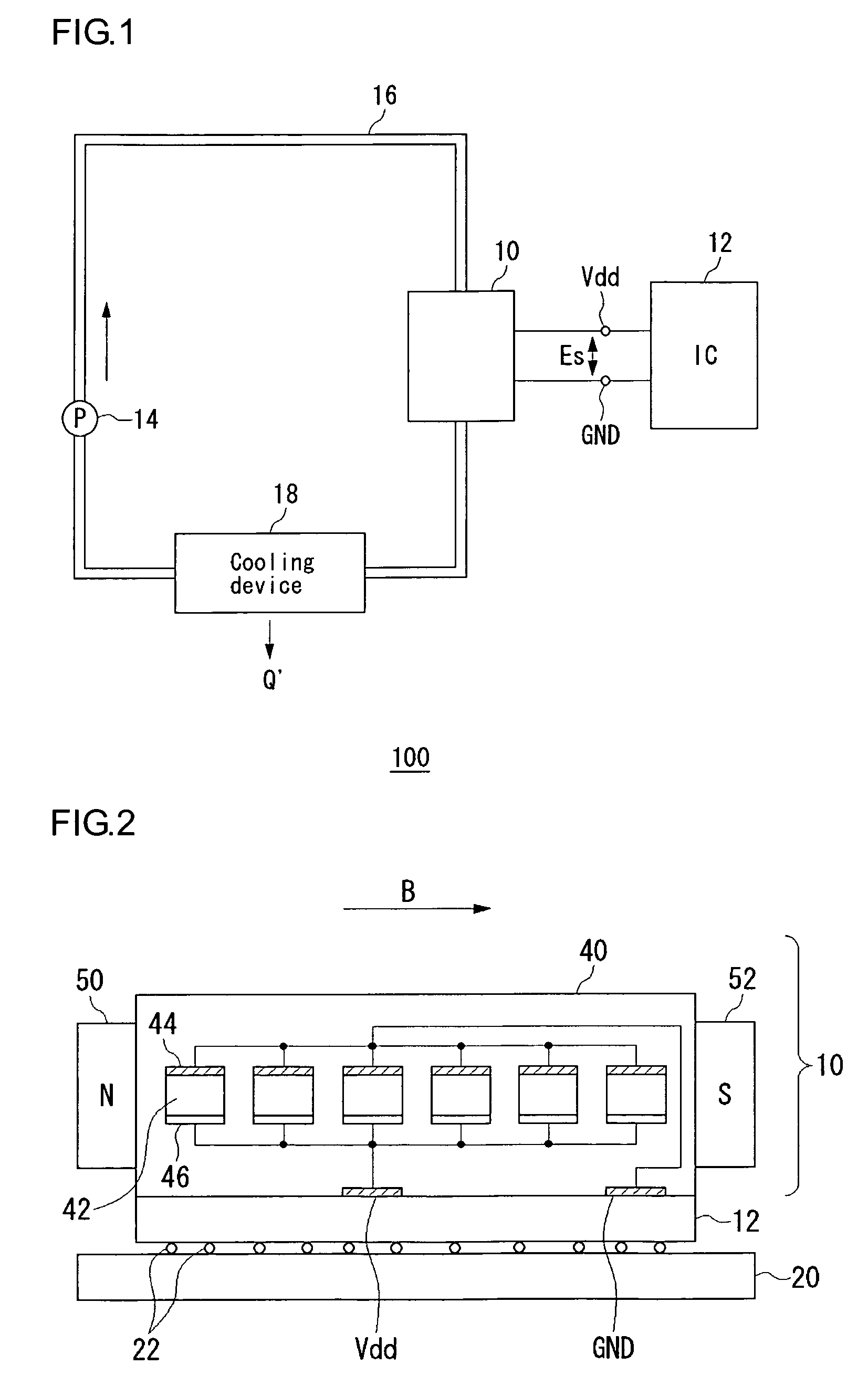
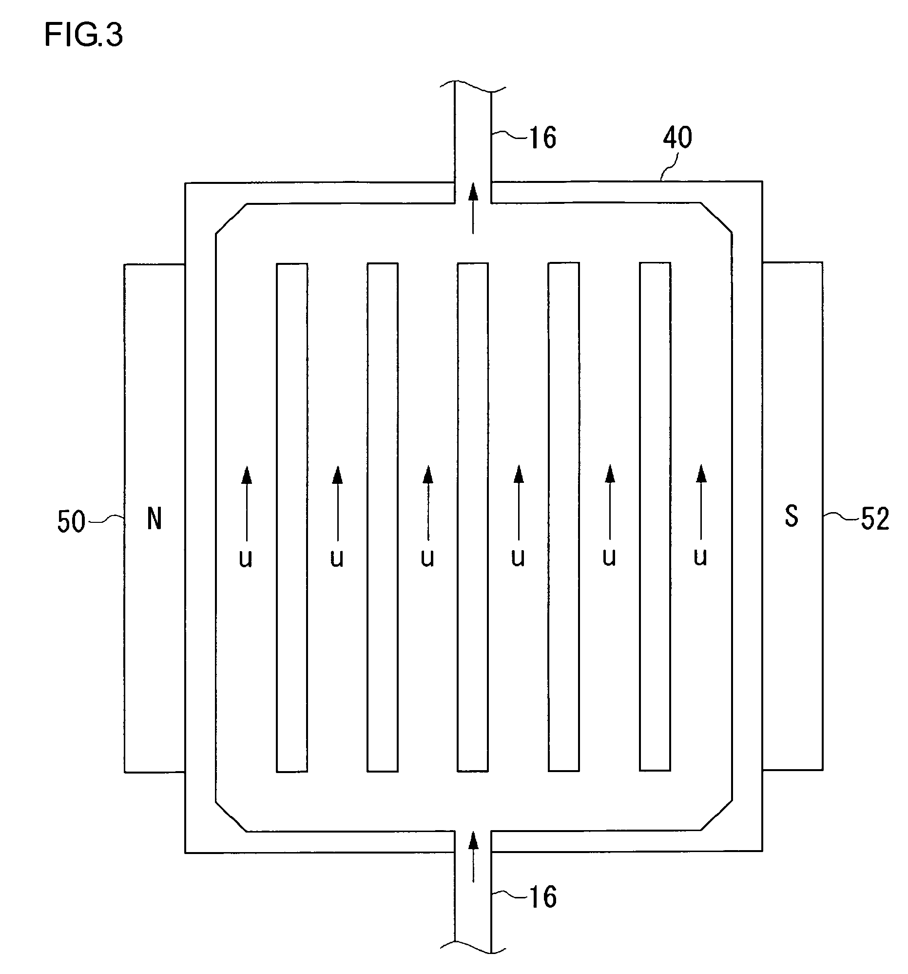
[0020]An aspect of the present invention relates to a power supply system. The power supply system includes: a substrate having a fluid channel formed therein; a pump allowing a conductive fluid to flow through the fluid channel formed within the substrate; a magnet which applies a magnetic field perpendicularly to a direction of flow of the conductive fluid; and an anode and a cathode which are respectively provided on two opposing surfaces so as to sandwich the fluid channel in parallel to the direction of appli...


PUM


Abstract

An electromotive cooling head includes a substrate, an N-pole magnet, and an S-pole magnet, and kept in intimate contact with the backside of the semiconductor integrated circuit so as to cover it. The substrate has a fluid channel having a micro-channel structure, through which a conductive fluid flows. An anode and a cathode are disposed to sandwich the fluid channel. The conductive fluid interacts with a magnetic field to thereby induce an electromotive force between the anode and the cathode. A circuit includes, on its backside, a power supply voltage terminal and a ground terminal, and is driven by the electromotive force induced in the electromotive cooling head.

Description

BACKGROUND OF THE INVENTION[0001]The present invention relates to power supply and cooling technologies, and more particularly to a power supply technology which is applied to semiconductor integrated circuits.[0002]In the design of LSIs, it has become very critical to take the amount of heat generation into account as a performance limit of the chip as semiconductor manufacturers move their manufacturing processes to increasingly finer design rules and achieve significantly larger packing densities. At high temperatures, the chip will malfunction or suffer from degradation in long-term reliability. Accordingly, various measures are taken against heat generation. For example, a heat sink is provided on the upper portion of a chip to liberate the heat generated from the chip.[0003]Recent LSIs, particularly high-performance microprocessors, may generate heat that cannot be dissipated by the heat sink. It is thus an everlasting challenge to improve the efficiency of heat dissipation.[0...

Claims


Application Information

Patent Timeline
Patent Type & Authority Patents(United States)
IPC IPC(8): H02K44/00H01L23/34
CPCF04B19/006H05K7/20272H01L2924/0002H01L2924/00
Inventor YAZAWA, KAZUAKITAKIGUCHI, IWAO
Owner SONY COMPUTER ENTERTAINMENT INC
Why Eureka
Try Eureka