Multi-antenna module

a technology of multi-antenna modules and antennas, applied in the field of multi-antenna modules, can solve the problems of increasing the difficulty of installing the antenna integration system, the radiation efficiency of the antenna integration system is difficult to increase, and the antenna system is difficult to integrate with electronic products, so as to reduce the layout space of the antenna, reduce the interference between the antenna and the effect of reducing the interferen

Inactive Publication Date: 2011-07-05
ADVANCED CONNECTEK INC
View PDF10 Cites 35 Cited by
  • Summary
  • Abstract
  • Description
  • Claims
  • Application Information

AI Technical Summary

Benefits of technology

One objective of the present invention is to provide a multi-antenna module, which comprises a ground plane, a primary conductor, a secondary conductor and a plurality of coupling conductors, and which features sharing radiation conductors and a ground plane, whereby the layout space of antennae is greatly reduced, and whereby the multi-antenna module of the present invention is easy-to-assemble for various electronic devices.
Another objective of the present invention is to provide a multi-antenna module, wherein the framework of the parallel primary radiation arm and secondary radiation arm can infinitely expand the number of antenna units in the same antenna structure, and wherein the interference between antennae is reduced, whereby the present invention has multiple operation frequency bands and can apply to multiple communication systems, and whereby the present invention achieves antenna miniaturization.
A further objective of the present invention is to provide a multi-antenna module, wherein the capacitive coupling effect of parallel radiation arms and the inductance of the radiation arms themselves form a high-pass or low-pass filter, whereby the isolation of antennae is effectively increased.
In a first embodiment of the present invention, the secondary radiation arm of the secondary conductor receives microwave signals of a first antenna from the first feeder cable. The microwave signals are then transmitted to the extension arm, the second short-circuit member, and the ground plane. Via the capacitive coupling effect of the secondary radiation arm and the primary radiation arm, the signals are coupled to the primary conductor. The primary conductor receives the electrically-coupled signals from the secondary radiation arm and further transmits the signals to the first short-circuit member and the ground plane. Thus, the primary radiation arm, the secondary radiation arm, the extension arm, the first short-circuit member, and the second short-circuit member jointly form the main radiation structure of the first antenna. Then, the primary conductor and the secondary radiation arm excite a first resonant mode of the first antenna, and the extension arm excites a second resonant mode of the first antenna. A capacitive effect is created between the coupling conductor and the extension arm, and an inductive effect is created in the coupling conductor itself. Then, a filter, which can effectively protect a second antenna from the interference of the signals of the first antenna, will be formed via appropriately adjusting the gap and the thickness and serpentinity of the coupling conductor.
In the first embodiment, the signal filters are formed by the integration structure of the ground plane, the primary conductor, the secondary conductor and the coupling conductor together with the capacitive coupling effect of the parallel radiation arms and inductance of the conductors. The signal filters can effectively reduce the mutual interference between the first antenna and the second antenna. Thus, additional spacing is unnecessary between two adjacent antennae, and the dimensions of the antenna system are greatly reduced. Further, a superior isolation can still be achieved thereby. As the antennae of the present invention share parts of the radiation conductors, the layout size of the antennae is greatly reduced, and the assembly process thereof is simplified.
In the second embodiment, the framework of parallel primary radiation arm and secondary radiation arm can infinitely expand the number of antenna units in the same antenna structure. Filters, which can effectively reduce the interference between antennae, can be formed via appropriately adjusting the capacitive coupling effect of parallel radiation arms and the inductance of the radiation conductors. Thereby, multiple antennae can be integrated into the same antenna structure to share the radiation conductors and greatly reduce the layout space of antennae. Thus, the present invention can achieve antenna miniaturization and multiple operation frequency bands and apply to many communication systems. Further, the present invention is easy-to-assemble for various electronic devices

Problems solved by technology

Such a layout should increase the difficulty of installing the antenna integration system and make the antenna system hard to integrate with electronic products.
However, the radiation efficiency of the antenna integration system is hard to obviously increase thereby.
In fact, the prior-art antenna integration system seldom achieves the announced function completely.

Method used


Image

  • Multi-antenna module
  • Multi-antenna module
  • Multi-antenna module

Examples


first embodiment

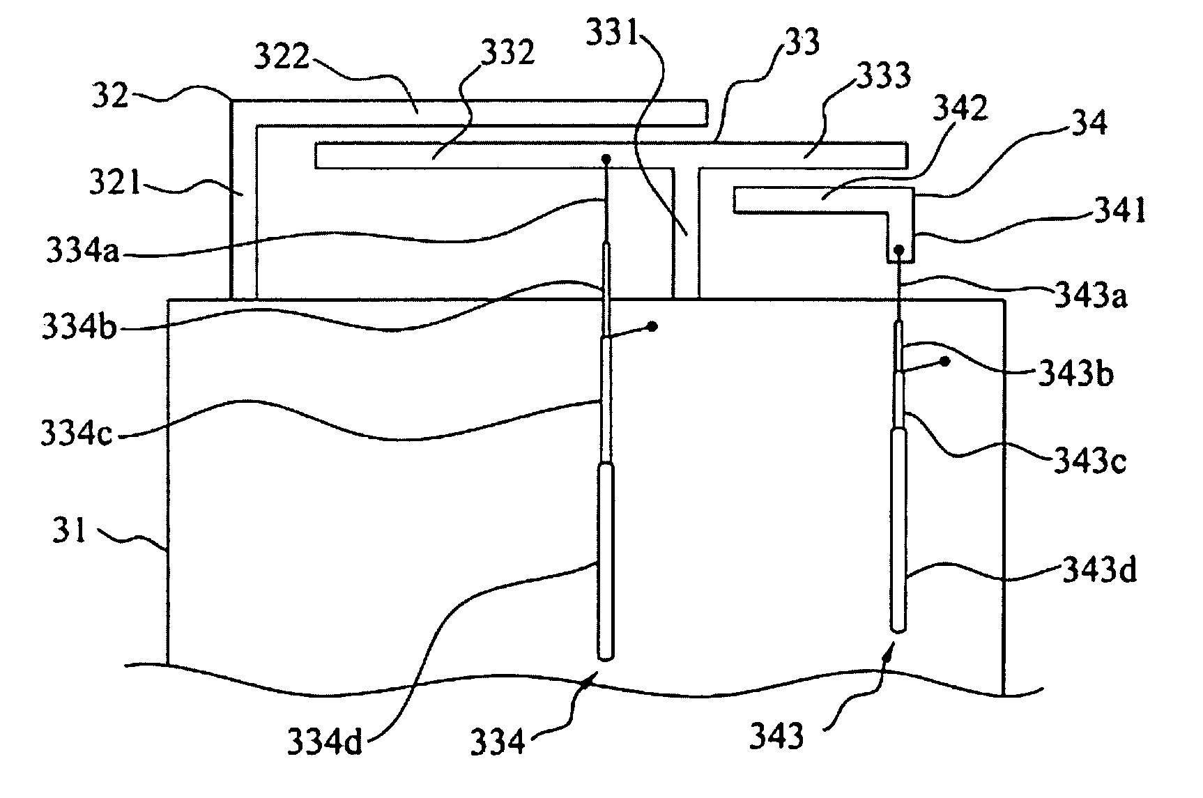
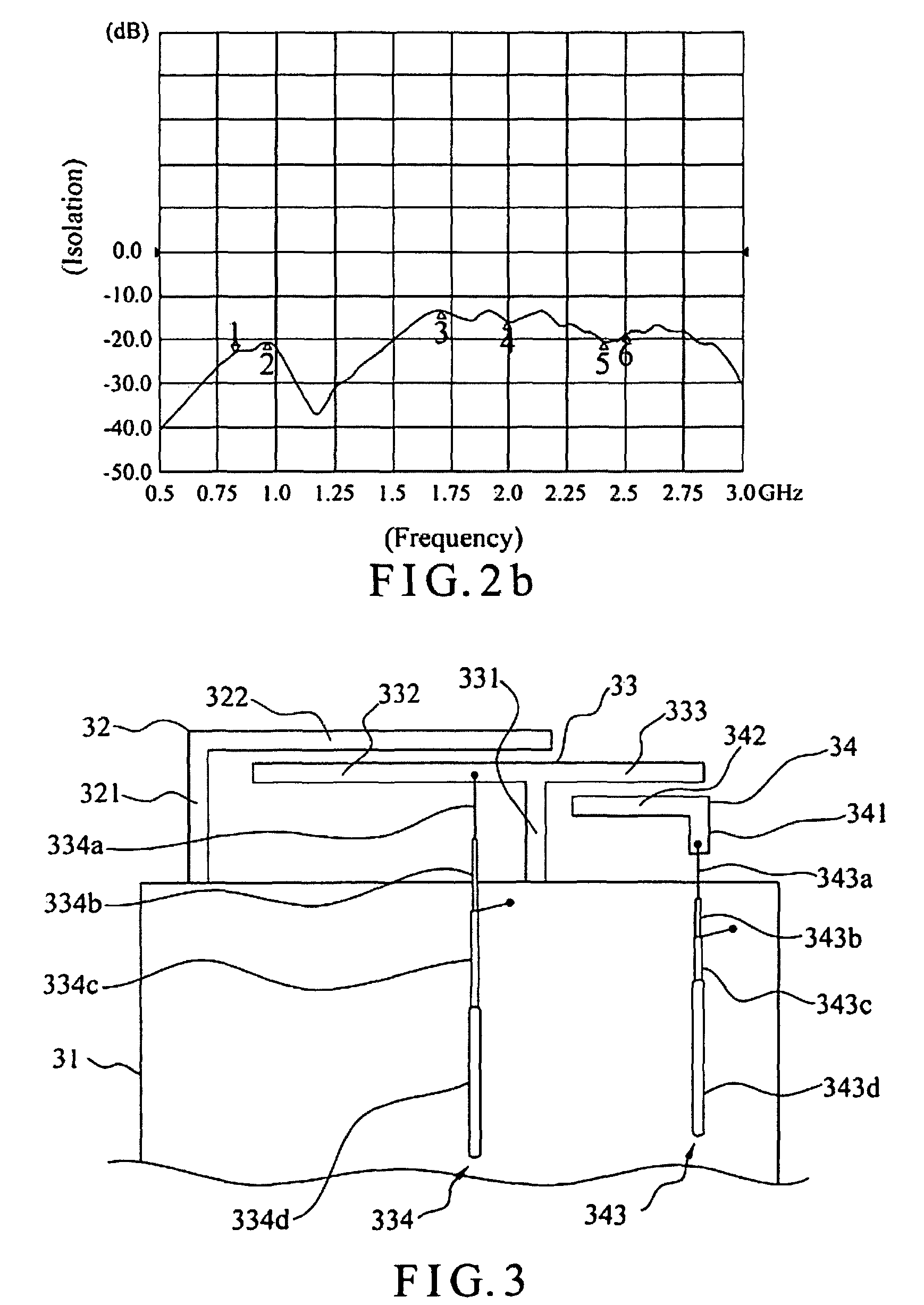
Referring to FIG. 3 a top view of a multi-antenna module according to the present invention, the multi-antenna module of the present invention comprises a ground plane 31, a primary conductor 32, a secondary conductor 33 and a coupling conductor 34. The primary conductor 32 further comprises a first short-circuit member 321 and a primary radiation arm 322. The secondary conductor 33 further comprises a second short-circuit member 331, a secondary radiation arm 332, an extension arm 333 and a first feeder cable 334. The coupling conductor 34 further comprises a feeder member 341, a coupling arm 342 and a second feeder cable 343.

One end of the first short-circuit member 321 of the primary conductor 32 is connected to the ground plane 31. One end of the primary radiation arm 322 is connected to the other end of the first short-circuit member 321, and the primary radiation arm 322 extends from the first short-circuit member 321 along a first direction. One end of the second short-circui...

second embodiment

The second embodiment is different from the first embodiment in that the primary conductor 52 has an additional first extension arm 523. The first extension arm 523 is connected to the joint of the first short-circuit member 521 and the primary radiation arm 522 and extends from the first short-circuit member 521 along the second direction. The second embodiment further has a second coupling conductor 55 arranged beside the first extension arm 523. The second coupling arm 552 of the second coupling conductor 55 and the first extension arm 523 of the primary conductor 52 are parallel to each other and have a gap therebetween. The third feeder cable 553 is connected to the second feeder member 551.

The second feeder member 551 receives a feed-in signal from the third feeder cable 553 and transmits the signal to the second coupling arm 552. The second coupling arm 552 couples the signal to the first extension arm 523, and the first extension arm 523 transmits the signal to the first sho...


PUM


Abstract

A multi-antenna module comprises a ground plane, a primary conductor, a secondary conductor and a plurality of coupling conductors, wherein the framework of the parallel primary radiation arm and secondary radiation arm can infinitely expand the number of antenna units in the same antenna structure. The capacitive coupling effect of parallel radiation arms and the inductance of the radiation arms themselves can effectively reduce the signal interference between antennae, whereby a plurality of antennae can be integrated to achieve antenna miniaturization. The primary conductor, the secondary conductor and the coupling conductors are all connected to the same ground plane, whereby the layout space is reduced, and the multi-antenna module is easy-to-assemble for various electronic devices.

Description

BACKGROUND OF THE INVENTION1. Field of the InventionThe present invention relates to a multi-antenna module, particularly to a multi-antenna module, wherein the number of antenna units can be infinitely expanded in the same antenna structure.2. Description of the Related ArtWith the popularization of wireless communication, there are also many advances in antenna technology. Particularly, many types of Combo antenna systems have been developed to meet the tendency of miniaturizing antennae and fabricating multi-frequency communication devices, wherein different antenna structures are integrated into a single antenna module to attain a multi-frequency function and reduce the sizes of antenna systems.Refer to FIG. 1. A Taiwanese patent No. I268010 discloses an antenna integration system for mobile phones, which comprises a baseplate 104, a planar Inverted F antenna 101, a monopole antenna 102, and a planar antenna 103. The planar Inverted F antenna 101 has a feeder point 105 and groun...

Claims


Application Information

Patent Timeline
Patent Type & Authority Patents(United States)
IPC IPC(8): H01Q1/24
CPCH01Q1/243H01Q9/42H01Q21/28
Inventor TSENG, YI-WEILIN, SHENG-CHIHCHIU, TSUNG-WENHSIAO, FU-REN
Owner ADVANCED CONNECTEK INC
Why Eureka
Try Eureka