Ultralow noise mode-locked laser and RF sinewave source

a laser and ultra-low noise technology, applied in the direction of wave amplification devices, laser details, electrical equipment, etc., can solve the problems of limited “quality factor” or q that are not overcome, the prior art oscillator also has problems, and the noise of the electronic oscillator is relatively high

Active Publication Date: 2011-07-12
UNIV OF CENT FLORIDA RES FOUND INC
View PDF13 Cites 15 Cited by
  • Summary
  • Abstract
  • Description
  • Claims
  • Application Information

AI Technical Summary

Benefits of technology

[0009]A secondary objective of the present invention is to provide methods, devices and systems for generating a precise optical timing signal that does not require a separate pumping laser or microwave source.
[0010]A third objective of the present invention is to provide a self-starting mode-locked laser opto-electronic oscillator for generating precise optical and electrical timing signals.
[0013]Preferred embodiments of the invention demonstrate the operation of an opto-electronic loop oscillator (OEO) that can use the longitudinal modes of an approximately 12.5 GHz harmonically mode-locked laser. Key attributes of the OEO are that it can generate high quality microwave and optical timing signals with low noise in contrast to conventional frequency synthesizers that require a frequency source and multiplication.
[0015]The method can further include the steps of suppressing the supermode noise of the harmonically mode-locked laser source, filtering the divided electrical beat pulses, and providing a Fabry-Perot Etalon as the filter.
[0022]The method can include suppressing the supermode noise of the harmonically mode-locked laser source, filtering the divided electrical beat pulses, and providing a Fabry-Perot Etalon as the filter.

Problems solved by technology

Despite widespread use, electronic oscillators are relatively noisy and lack adequate stability for applications that require very high stability and spectral purity.
Additionally, the prior art oscillators also has problems such as limited “quality factor” or Q that are not overcome.
Opto-electronic oscillators can convert light energy into stable and spectrally pure microwave signals, but fail to overcome all the problems of the prior art.

Method used


Image

  • Ultralow noise mode-locked laser and RF sinewave source
  • Ultralow noise mode-locked laser and RF sinewave source
  • Ultralow noise mode-locked laser and RF sinewave source

Examples


Embodiment Construction

[0044]Before explaining the disclosed embodiments of the present invention in detail it is to be understood that the invention is not limited in its application to the details of the particular arrangements shown since the invention is capable of other embodiments. Also, the terminology used herein is for the purpose of description and not of limitation.

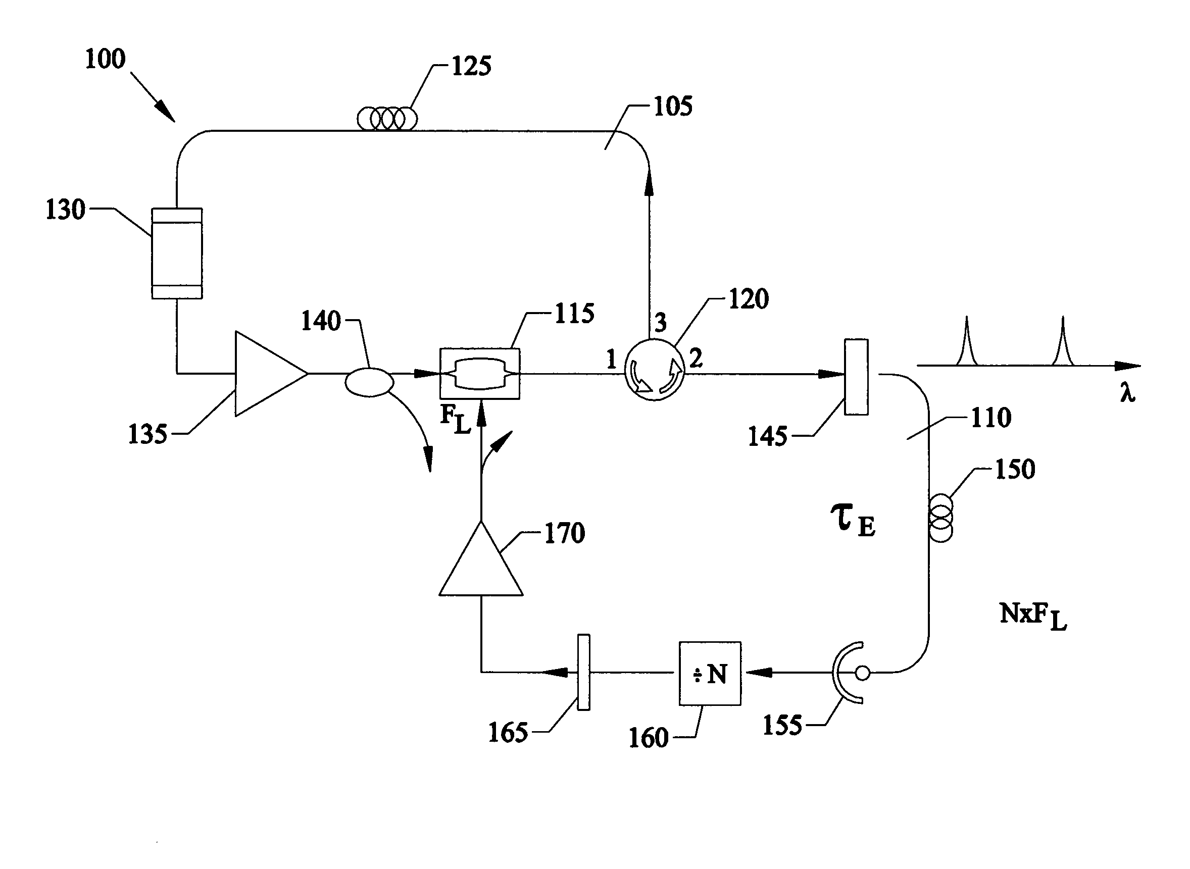
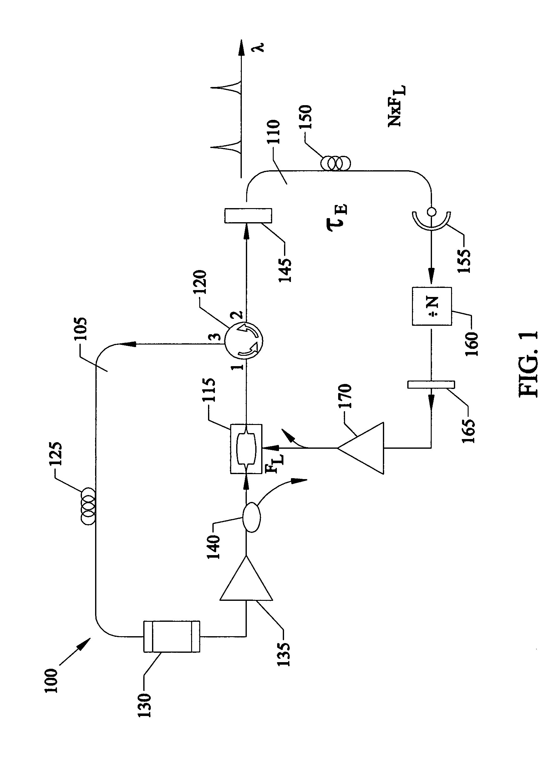
[0045]A preferred embodiment of the novel ultra-low noise mode-locked laser and RF sinewave source 100 is shown in FIG. 1. The optical loop 105 of the opto-electronic oscillator 100 forms an optical ring laser and is comprised of modulator 115, optical circulator 120, optical delay 125, Fabry-Perot Etalon 130, optical gain 135, and optical coupler 140. Optical gain 135 can be a device such as a semiconductor optical amplifier (SOA) or an erbium-doped fiber amplifier (EDFA). The modulator 115 can be a LiNb03 Mach-Zehnder modulator or similar. Optical delay 125 can be a spool of fiber of approximately 100 meters in length. The electric...


PUM


Abstract

Systems, devices and methods of generating both a precision electrical timing signal as well as a precision optical timing signal. A novel, modified opto-electronic loop oscillator is used to drive a harmonic mode-locked laser. A novel opto-electronic loop has a larger “Q” factor by increasing the electrical loop oscillating frequency ω0 by using a beat note created by the selection of two optical longitudinal modes from the mode-locked laser. The beat note is detected and divided down to drive a modulator that mode-locks the laser. The frequency division stage also reduces the noise.

Description

[0001]This is a Divisional of application Ser. No. 11 / 029,974 filed Jan. 5, 2005 now U.S. Pat. No. 7,492,795 which claims the benefit of U.S. Provisional Patent Application 60 / 534,435 filed on Jan. 6, 2004.FIELD OF INVENTION[0002]This invention relates to generating timing signals and, more specifically, in particular to methods, devices and system for using opto-electronic oscillators for the generation of precision timing signals in laser type sources for applications such as computer systems, satellite and navigation systems, and guidance and control systems.BACKGROUND AND PRIOR ART[0003]Electronic oscillators used to generate precision timing signals are pervasive in virtually every application of electronic devices, instruments, and systems. Despite widespread use, electronic oscillators are relatively noisy and lack adequate stability for applications that require very high stability and spectral purity.[0004]Additionally, the prior art oscillators also has problems such as li...

Claims


Application Information

Patent Timeline
Patent Type & Authority Patents(United States)
IPC IPC(8): H01S3/13
CPCH01S3/1109H01S3/1121H01S3/136H01S3/06791H01S3/08036H01S3/107H01S3/1305
Inventor DELFYETT, PETER J.GEE, SANGYOUNCHOI, MYOUN-TAEK
Owner UNIV OF CENT FLORIDA RES FOUND INC
Why Eureka
Try Eureka