Optical data transmission system

a technology of optical data transmission and optical data, applied in the field of optical data transmission system, can solve the problem of impracticality of providing every user device, and achieve the effect of reducing connector quality requirements and simplifying system assembly

Active Publication Date: 2011-07-12
SCHOFIELD TECH
View PDF20 Cites 11 Cited by
  • Summary
  • Abstract
  • Description
  • Claims
  • Application Information

AI Technical Summary

Benefits of technology

[0022]In an embodiment in which all of the data signals have a common wavelength or are within the specified wavelength range, this means that all of the ONUs may be identical. As mentioned above, this does not require that the ONUs provide light having a common wavelength, but rather that ONUs only need similar components to provide undefined wavelengths within the specified wavelength range. The ONUs are similar in the sense that no wavelength selection of source components is needed. Accordingly, this simplifies the assembly of the system since it is not necessary to provide certain ONUs to certain users. In addition, the cost of providing a plurality of identical ONUs is cheaper than the cost of providing different wavelength specific ONUs.
[0023]Preferably multimode fibre can be used between the ONUs and the kerb, between the kerb and the hub, or between both, to relieve connector quality requirements.

Problems solved by technology

For generation and transmission of data in the upstream direction, it is impractical to provide every user device 114 with a laser source operating within its assigned wavelength band.

Method used


Image

  • Optical data transmission system
  • Optical data transmission system
  • Optical data transmission system

Examples


Embodiment Construction

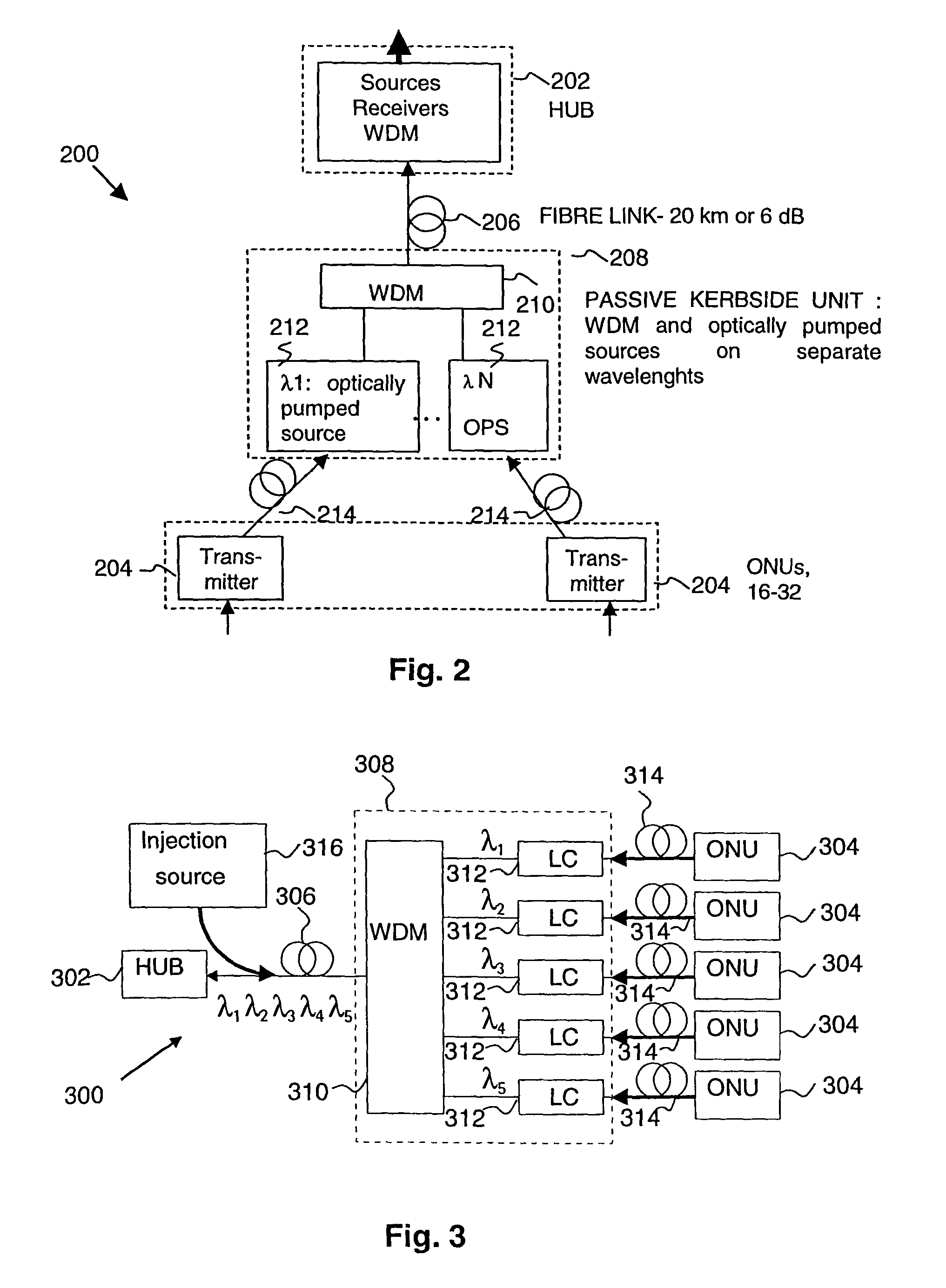
[0048]FIG. 2 shows a WDMA system 200. The system 200 comprises a central office (CO) or hub 202 connected to user devices or optical network units (ONUs) 204. The hub 202 is connected by an optical fibre link 206 to a kerbside unit 208. The optical fibre link is typically kilometers, or tens of kilometers, long. The kerbside unit 208 comprises a wavelength division multiplexer (WDM) 210 and a plurality of optically pumped sources 212. Each optically pumped source 212 is associated with a respective ONU 204. The ONUs 204 are connected separately to the kerbside unit 208 by respective optical fibres 214. The kerbside unit 208 is at a kerb location.

[0049]In this embodiment only two ONUs 204 are shown connected to the kerbside unit 208 although it should be understood that there would be a plurality of such ONUs, for example 16 to 32 units. Furthermore, there may also be a plurality of kerbside units 208 connected to a single hub 202.

[0050]In the following description, a downstream dire...


PUM


Abstract

An optical data transmission system having a hub, an optical router, and a plurality of optically pumped sources at a curb location, and a plurality of optical network units (ONUs). The ONUs generate and transmit respective data modulated pumping light to the curb location where it is received by the optically pumped sources, which convert it into the wavelength channels having predefined wavelength ranges assigned to respective ONUs. The optical router routes the wavelength channels for transmission to the hub.

Description

BACKGROUND OF THE INVENTION[0001]1. Field of the Invention[0002]The invention relates to an optical data transmission system. It is particularly, but not exclusively, related to a system comprising a passive optical fibre network.[0003]2. Description of Related Art[0004]In order to provide broadband telecommunications, optical transmission systems have been developed. Typically such systems transmit optical signals along optical fibre in the wavelength range of 1300 to 1600 nm. In order to provide multiple access for a plurality of users, it has been proposed for optical transmission systems to use wavelength division multiple access (WDMA).[0005]An optical transmission system 110 is shown in FIG. 1. The system 110 comprises a central office (CO) or hub 112 connected to groups of user devices or optical network units (ONUs) 114. In this embodiment only one group 116 is shown although it will be understood that there would be a plurality of such groups. The hub 112 is connected by a ...

Claims


Application Information

Patent Timeline
Patent Type & Authority Patents(United States)
IPC IPC(8): H04J14/00H04B10/272H04J3/16H04J14/02
CPCH04J14/0226H04J14/0282H04Q11/0067H04J14/0246H04J14/0247H04J14/025H04J14/0252H04Q2011/0086
Inventor POHJOLA, OLLI-PEKKATERVONEN, ARIJARVINEN, HARRI T.OKSANEN, MARKKU
Owner SCHOFIELD TECH
Why Eureka
Try Eureka