Method and device for irrigation of body cavities

a body cavity and irrigation method technology, applied in the field of endoscopic surgery, can solve the problems of resistance reconfirmation and loss of pressure in the system, and achieve the effects of increasing the flow through the body cavity, increasing the flow rate, and keeping the liquid clear

Active Publication Date: 2011-07-19
TENNESSEE MEDICAL INNOVATIONS INC
View PDF12 Cites 56 Cited by
  • Summary
  • Abstract
  • Description
  • Claims
  • Application Information

AI Technical Summary

Benefits of technology

[0019]Secondly, the resistance in the system is reconfirmed during routine use of the system. This reconfirmation is made by a temporary halt of flow by stopping both the inflow and outflow pumps instantaneously. The outflow pump can alternatively be replaced with a valve, which stops the flow in the same manner. This alternative can be used when the liquid management system only operates an irrigation pump. The valve function may comprise means to pinch tubing. At that instant, the pressure is high at the inflow pump, where the pressure is also measured, and lower in the body cavity. The liquid is trapped between the following components: the roller of the inflow peristaltic pump; the cavity of the pressure transducer; the tubing from the pressure transducer to the endoscope connector with shutoff valve; endoscope connector with shutoff valve; the endoscope; the body cavity; the liquid output from the body cavity such as a cannula, shaver or other instrument; the tubing from the output instrument to the rollers of the outflow peristaltic pump, or a valve function; and finally the rollers of the outflow peristaltic pump or a valve function. During the next phase, being approximately 2 seconds, the pressure difference between the inflow pump and the body cavity causes a diminishing flow to the body cavity. If the time the pumps are stopped is long enough, the pressure difference will diminish by a basic rule of communicating vessels. The time constant of this diminishing flow is a representation of resistance. It is to be noted that it is not necessary to hold the pumps stopped for the time it takes for the flow to become zero. An extrapolation of the pressure signal is fulfilling for the purpose of determining an end pressure. This minimizes the time the body cavity is not irrigated. The reconfirmation can be initialized manually by pressing a button, or automatically by regular intervals controlled by the software, or automatically triggered by software if pressure fluctuations occur that indicate that the surgical situation might have influenced resistance.
[0023]Compliance values can be calculated by the pump system, which measures the pressure as mentioned above, and the flow is proportional to the rotational speed of the roller pump heads. Calculated compliance values are also stored in a memory, and can be used in several ways. One first consideration is the effect the compliance has on the process of reconfirmation of resistance values. The reconfirmation of resistance values is adjusted for as a result of the compliance as the aforementioned time constant is affected by compliance. Another use of the compliance value is to indicate these to the operator. This has the benefit of warning the operator of the risk that excessive liquid may be introduced. The indication can be that of a figure in a display, a “bar indicator” in a display, or a buzzer that emits sound at a predetermined level of compliance. The compliance value can also affect the operation of the pump system by limiting the pressure it produces, to avoid tissue damage.
[0033]The disposable material by the optical detector in the outflow path may be smudged with body fats as a result of the surgical process. The signal processing can compensate for this slow build up of offset of signal from the optical detector.
[0034]Rinsing of the body cavity may be initiated manually by the press of a button or a foot operated switch, and results in an increased liquid flow. However the detection of blood or debris may automatically initiate a rinsing process. This detection may in general increase flow through the body cavity and this will beneficially keep the liquid clear. Such increase may be gradual or in steps to achieve the target of a clear viewing filed for the surgeon. Whether decided by a user or automatically by the system, the rinsing of the body cavity can be terminated manually or automatically. Optionally the pressure may be elevated to depress bleeding. This elevation of pressure is preferred as blood is detected, but not debris. Increasing pressure over the patients' perfusion blood pressure reduces the bleeding. The result is that a clear viewing field is maintained automatically and the operator can focus on the endoscopic procedure instead of manually optimizing the liquid management system to give visibility. The operation time will thereby be reduced in most procedures resulting in fewer complications for the patient.

Problems solved by technology

Due to resistance in the liquid pathway, there is a loss of pressure.
Flow turbulence in the irrigation system causes unlinearities.
Secondly, the resistance in the system is reconfirmed during routine use of the system.

Method used


Image

  • Method and device for irrigation of body cavities
  • Method and device for irrigation of body cavities
  • Method and device for irrigation of body cavities

Examples


example 1

Smart Vision / LED

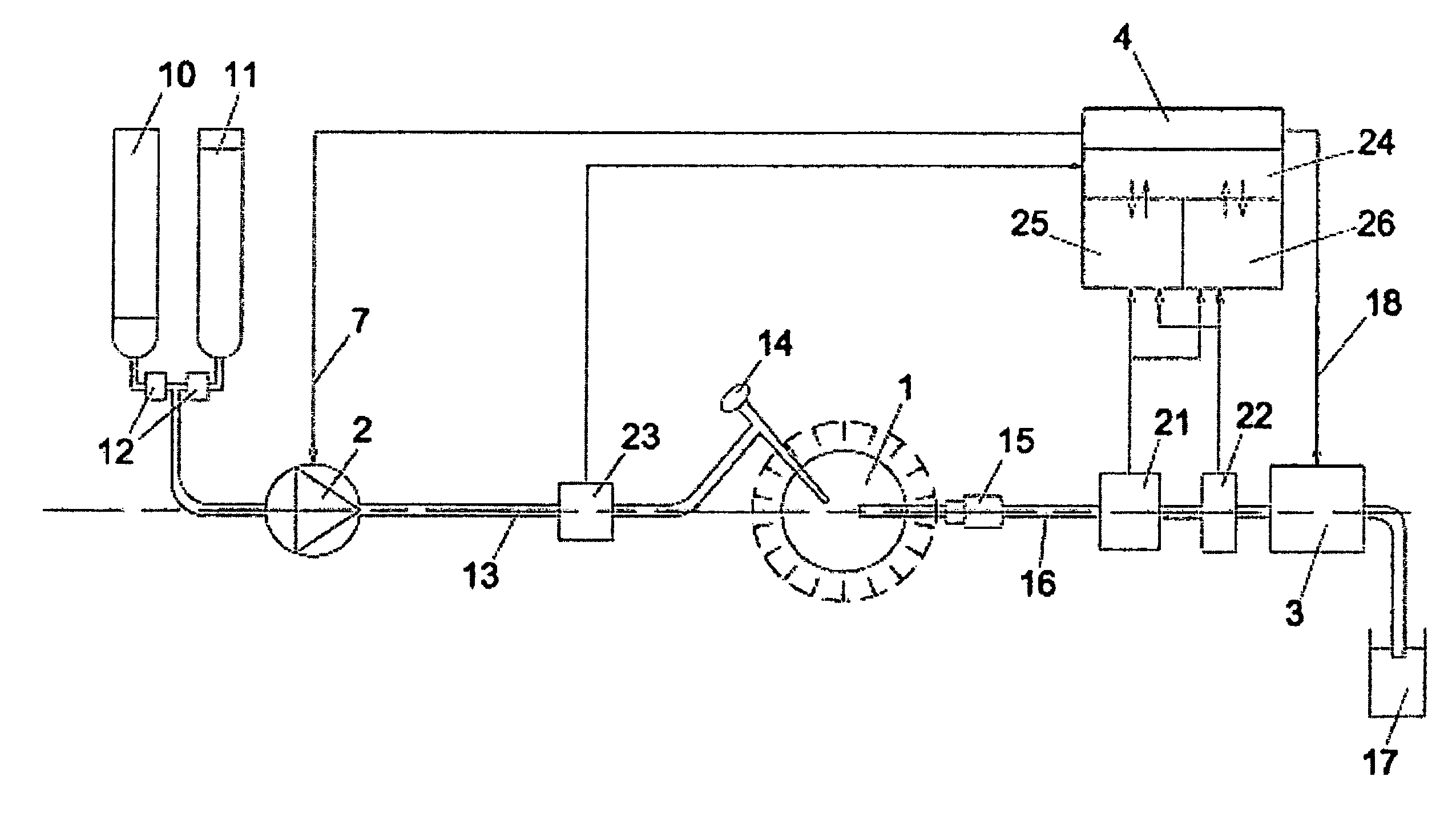
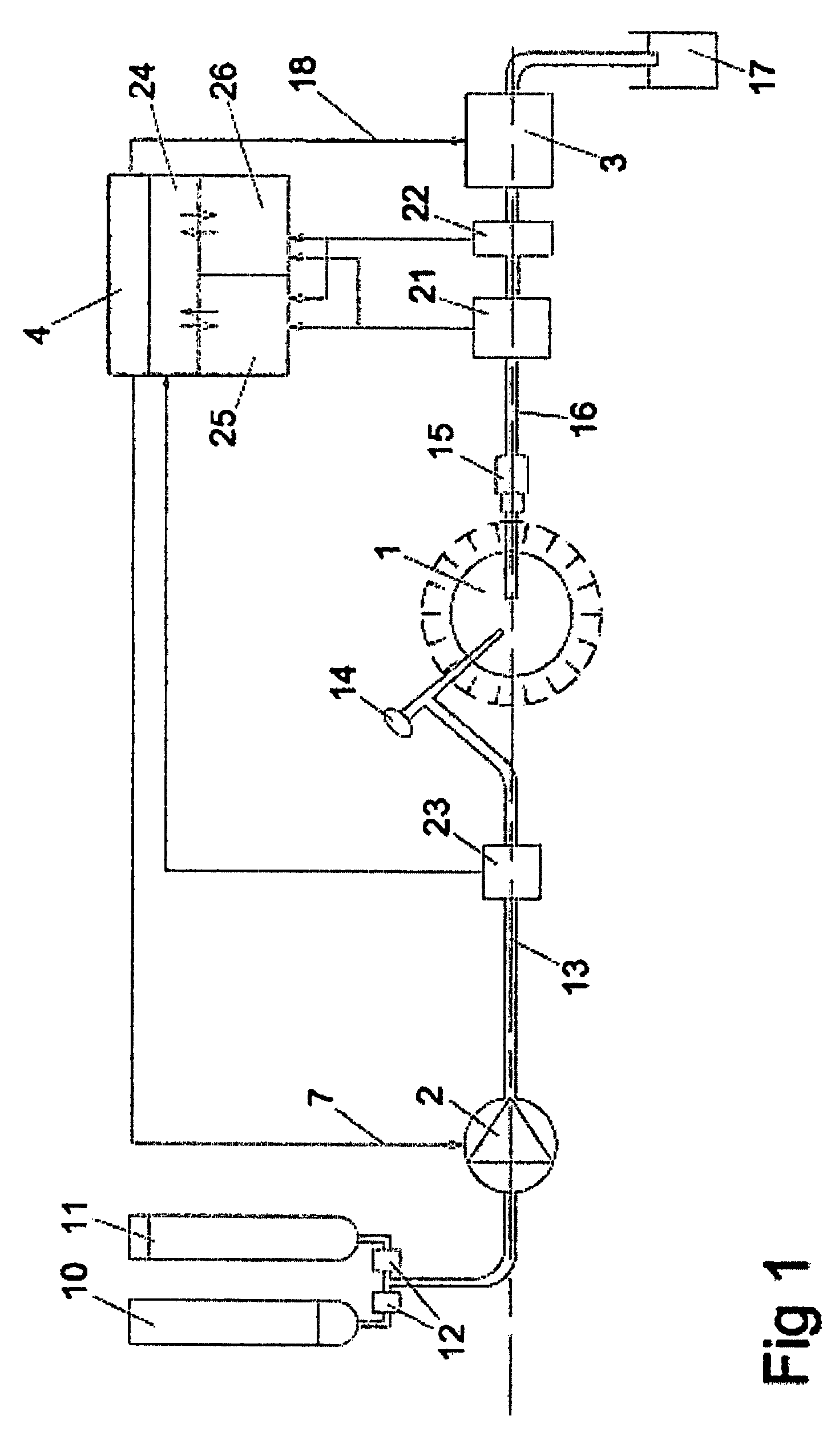
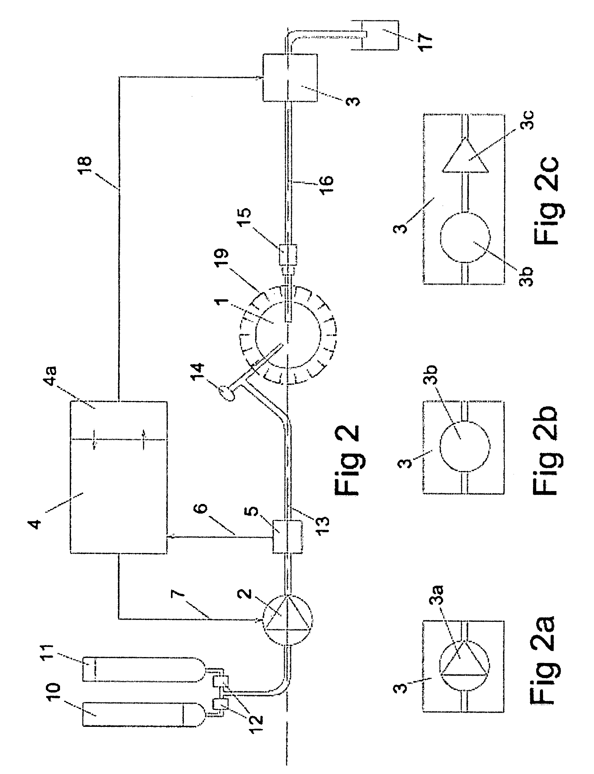
[0077]Below is an example of a technique to detect and distinguish blood and debris in the liquid that is aspirated from a knee joint during an arthroscopic procedure while using an irrigation system for body cavities. Signals from this detection is used to control the pressure in, and liquid flow through the knee joint in a manner that keeps it clear from blood and debris for good viewing with the arthroscope. If debris is detected, the flow through the knee joint is automatically elevated to efficiently rinse it. If blood is detected, the pressure is also automatically elevated, to inhibit blood from leaving the broken vessels, by overcoming the blood pressure.

[0078]Work is performed in the knee with surgical tools such as forceps, scissors, rotating burrs and drills. Various forceps are used to detach tissue, and as a result some of this tissue will float in the liquid in the surgical site. These particles of tissue may be of bone, cartilage, small tissue fragment...

example 2

Detached Sensors

[0088]Fitting the optical sensors (21, 22) on a blood vessel near to, directly adjacent to the surgical instrumentation, or even within the surgical instrumentation is advantageous, as the reaction time as the debris and / or blood leaves the surgical site and as it reaches the optical sensors is reduced. This can be accomplished by use of a cable or wireless detector and a battery operated detector with wireless data transfer. The detector can be fitted on the cannula where the liquid normally is withdrawn from the surgical site as shown in the example in FIG. 14. In this example, wires (36) are used to connect the sensors to the operating control device (27). If the detector is fitted on or within the housing of a shaver, the wiring for the optical detector may be enclosed in the cable for the shaver.

example 3

Detached Sensing

[0089]As shown in the example in FIG. 15, the optical sensors (21, 22) can be fitted in the operating control device (27), but the detection is made within the surgical instrumentation. Instead of electrically connecting the optical sensors to the operating control device (27), they are optically be connected to the surgical instrumentation by use of optical fibres (37).


PUM


Abstract

A pressure and a vision regulation method and device for irrigation of a body cavity (1), in which an inflow liquid pump (2) pressurizes the irrigation liquid in a feed line (13) and an outflow device (3) or an external suction source (20) drains the irrigation liquid from the body cavity (1) through a tubing (16) into a waste container (17). A control unit (4) controls either the inflow liquid pump (2) only or both the inflow liquid pump (2) and the outflow device (3) depending on an inflow irrigation liquid pressure from a pressure sensor (5). The method and the device are combined with a method for detecting blood cells, red blood cells, haemoglobin and / or debris in liquid coming from a surgical site to provide an automatic control and rinsing system with clear vision in the viewing area of the operational site.

Description

CROSS-REFERENCE TO RELATED APPLICATIONS[0001]This application is a continuation-in-part of copending U.S. patent application Ser. No. 11 / 729,357 filed Mar. 28, 2007, which claims priority from Swedish application no. 0600718-1 filed Mar. 30, 2006.TECHNICAL FIELD OF THE INVENTION[0002]This invention relates to the medical field of endoscopic surgery, and in particular the management of liquid that is irrigated into the surgical site during endoscopic procedures.BACKGROUND OF THE INVENTION[0003]During endoscopic surgical procedures, a surgical site such as a knee joint, shoulder joint or other cavity in the body of a human or animal is viewed with an endoscope. Further in this patent application, the surgical site for an endoscopic procedure is referred to as the body cavity. The body cavity is irrigated with a clear liquid by means of a pump. This pump is further in this patent application referred to as an inflow liquid pump. The clear liquid is as a rule saline, and the pump is usu...

Claims


Application Information

Patent Timeline
Patent Type & Authority Patents(United States)
IPC IPC(8): A61M1/00
CPCA61B1/015A61B1/126A61M3/0258A61M2205/331A61M2205/3313A61M2205/702A61M3/0216A61M3/0208A61M3/0204A61M3/022A61M3/0212A61M2205/50A61M3/0202
Inventor MOLLSTAM, ANDERSMILTON, SVENMOVIN, TOMAS
Owner TENNESSEE MEDICAL INNOVATIONS INC
Why Eureka
Try Eureka