Multi X-ray generating apparatus and X-ray imaging apparatus

a generating apparatus and a technology for imaging apparatus, applied in nuclear engineering, applications, instruments, etc., can solve problems such as difficulty in adjusting radiation quality and dose conditions, and achieve the effects of high speed, low dose, and high contrast x-rays

Inactive Publication Date: 2011-08-02
CANON KK
View PDF28 Cites 63 Cited by
  • Summary
  • Abstract
  • Description
  • Claims
  • Application Information

AI Technical Summary

Benefits of technology

[0011]The present invention has been made in consideration of the above problems. Exemplary embodiments of the present invention provide an X-ray generating apparatus and X-ray imaging apparatus which can obtain a high-contrast X-ray image with a low dose at high speed by increasing the degree of freedom in selecting a radiation quality and irradiation position in an X-ray source.

Problems solved by technology

In addition, since the number of focal spots of the X-ray source is also limited to about two, it is difficult to adjust radiation quality and dose conditions in accordance with a body part of an object and its shape and to obtain an X-ray image with high quality.

Method used


Image

  • Multi X-ray generating apparatus and X-ray imaging apparatus
  • Multi X-ray generating apparatus and X-ray imaging apparatus
  • Multi X-ray generating apparatus and X-ray imaging apparatus

Examples


first embodiment

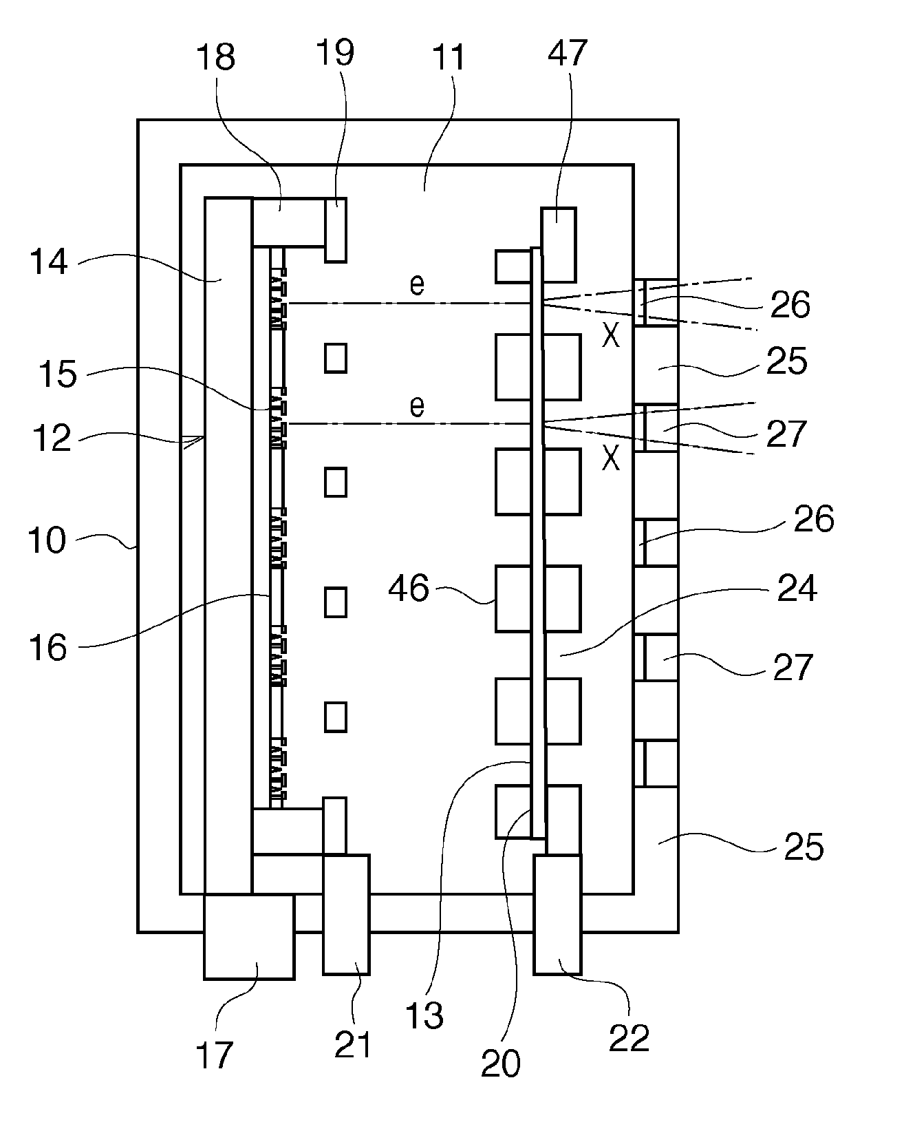
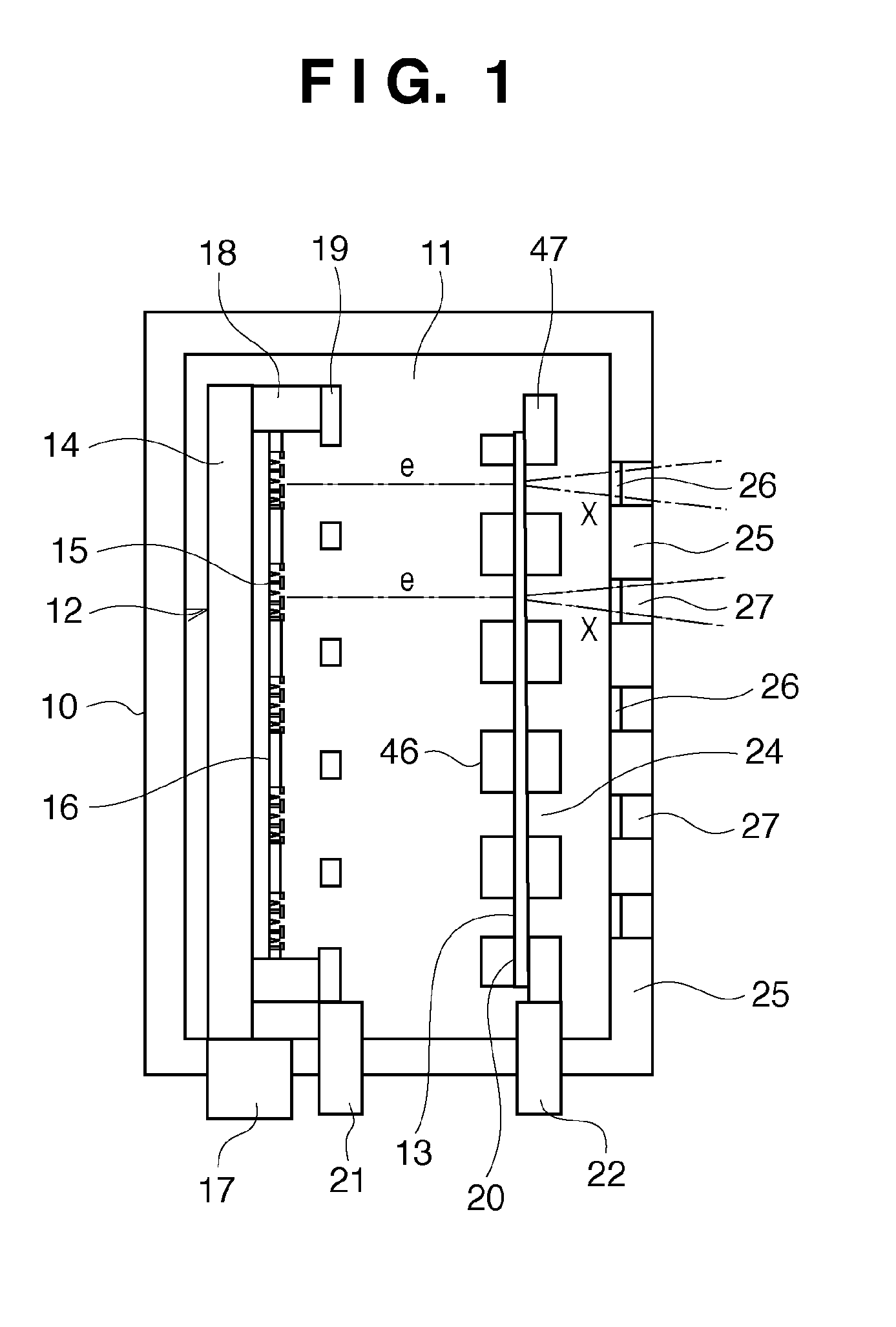
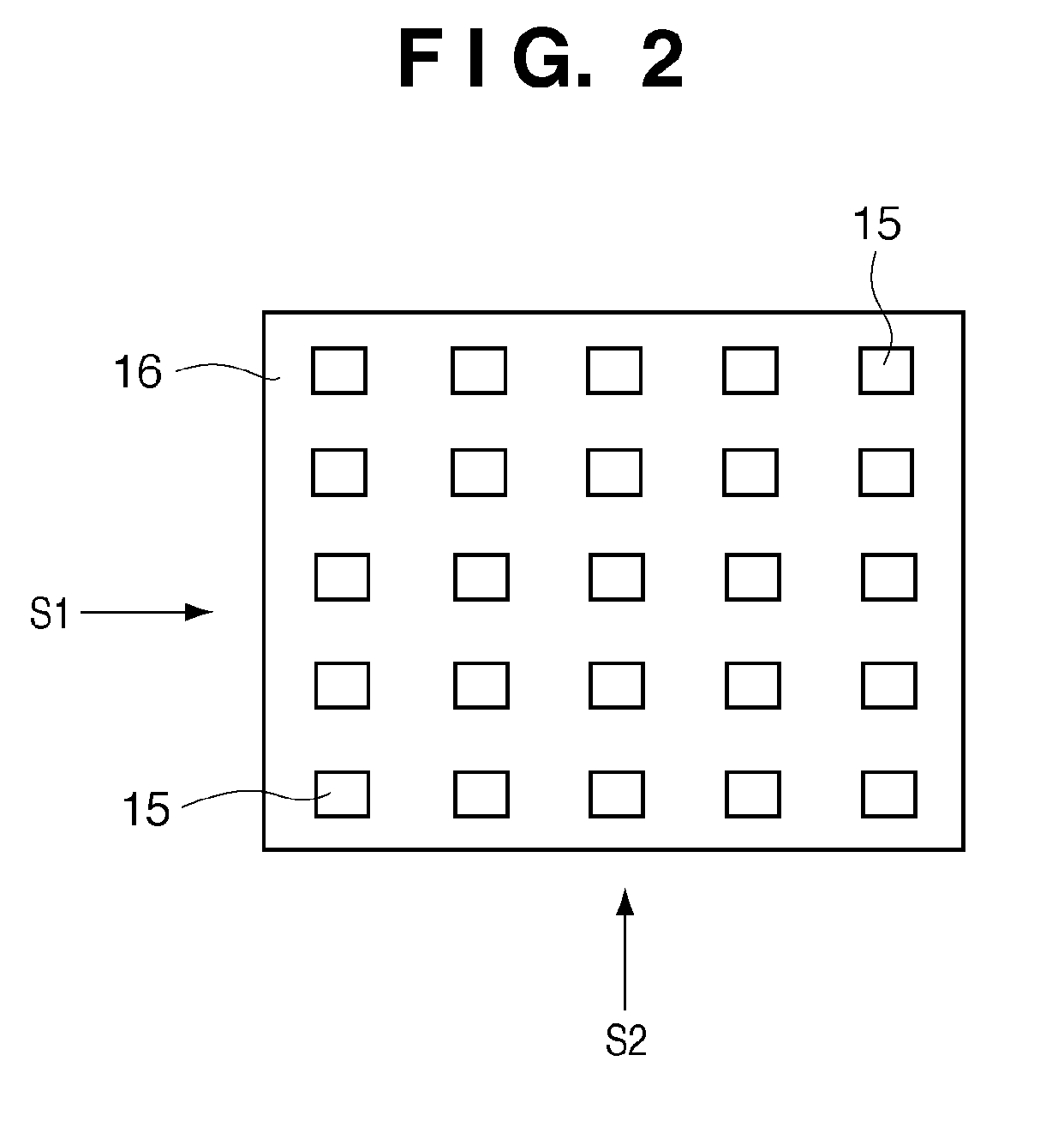
[0034]FIG. 1 is a view showing an example of the arrangement of a multi X-ray generating apparatus 10 as a multi X-ray source. Referring to FIG. 1, a vacuum chamber 11 incorporates a multi electron beam generating unit 12 as a multi electron source and a transmissive target 13 as a multi X-ray source. The multi electron beam generating unit 12 includes an element substrate 14 and an element array 16 on which a plurality of electron emitting elements 15 are arrayed. The electron emitting elements 15 function as electron sources. A driving unit 17 controls the driving of the electron emitting elements 15. A lens electrode 19 fixed to an insulator 18 and an anode electrode 20 are provided to control electron beams e emitted from the electron emitting elements 15. High voltages are applied to the lens electrode 19 and the anode electrode 20 via high voltage introducing portions 21 and 22.

[0035]The transmissive target 13 on which the generated electron beams e impinge is discretely arran...

second embodiment

[0049]In the first embodiment, the transmissive target 13 which outputs X-rays with different radiation qualities in accordance with the generation locations of X-rays is implemented by a multi target. The second embodiment exemplifies a case in which such a transmissive target is implemented by a multi filter in which a plurality of filters having different X-ray absorption characteristics with respect to X-rays are arranged.

[0050]FIGS. 7A and 7B are views showing an example of the arrangement of a transmissive target 13 according to the second embodiment, and show an example using a multi filter as an X-ray absorbing plate. As shown in FIG. 7A, in the transmissive target 13, filters are independently arranged at target positions opposite to electron emitting elements 15. Filters A43 and B44 are made of different materials. FIG. 7B is a sectional view of the transmissive target 13. The multi filter including the filters A43 and B44 is arranged on a surface of a substrate 45 which i...

third embodiment

[0054]An application of this X-ray source having a multi radiation quality characteristic will be described next with reference to FIGS. 9 to 11. FIG. 9 is a view showing a transmissive target 13 according to the third embodiment. This embodiment exemplifies a case in which the transmissive target 13 is formed by combining the multi target described in the first embodiment with the multi filter described in the second embodiment.

[0055]The transmissive target 13 of the third embodiment is obtained by combining a multi target with a multi filter so as to match irradiation conditions for an object. In this case, filters are arrayed in descending order of the radiation quality of X-rays (descending order of effective energy), i.e., in the order of (3), (2), and (1). In each of target groups A, B, and C, targets are sequentially arrayed upward (from c to a) in descending order of radiation quality. That is, in the transmissive target 13 shown in FIG. 9, a plurality of different types of ...


PUM


Abstract

A multi X-ray generating apparatus which has a plurality of electron sources arranged two-dimensionally and targets arranged at positions opposite to the electron sources includes a multi electron source which includes a plurality of electron sources and outputs electrons from driven electron sources by selectively driving a plurality of electron sources in accordance with supplied driving signals, and a target unit which includes a plurality of targets which generate X-rays in accordance with irradiation of electrons output from the multi electron source and outputs X-rays with different radiation qualities in accordance with the generation locations of X-rays. The generation locations and radiation qualities of X-rays from the target unit are controlled by selectively driving the electron sources of the multi electron source.

Description

RELATED APPLICATIONS[0001]This application claims the benefit of Japanese Patent Application No. 2008-048827, filed Feb. 28, 2008, the entire contents of which are hereby incorporated by reference.BACKGROUND OF THE INVENTION[0002]1. Field of the Invention[0003]The present invention relates to a multi X-ray generating apparatus used for nondestructive radiography, diagnosis, and the like in the fields of medical equipment and industrial equipment which use X-ray sources, and an X-ray imaging apparatus using the multi X-ray generating apparatus.[0004]2. Description of the Related Art[0005]In general, an X-ray tube uses a thermion source as an electron source, transmits the thermions from a filament heated to a high temperature to a Wehnelt electrode, extraction electrode, acceleration electrode, and lens electrode, and accelerates an electron beam into a high-energy electron beam. After shaping the electron beam into a desired shape, the X-ray tube generates X-rays by irradiating an X...

Claims


Application Information

Patent Timeline
Patent Type & Authority Patents(United States)
IPC IPC(8): H01J35/08
CPCA61B6/00A61B6/4028A61B6/4035A61B6/4233A61B6/482H01J35/065H01J35/08A61B6/4007A61B6/405H01J2235/062H01J2235/068H01J2235/087H01J35/112H01J35/116G03B42/02H01J35/00H05G1/00
Inventor OKUNUKI, MASAHIKOTSUJII, OSAMUSHIMIZU, SATOSHIOGURA, TAKASHI
Owner CANON KK
Why Eureka
Try Eureka