
Approach for improved fuel vaporization in a directly injected internal combustion engine

a technology of fuel vaporization and direct injection, which is applied in the direction of electrical control, process and machine control, etc., can solve the problems of further reducing the vaporization rate of direct injection fuel, increasing emissions, etc., and achieves the effect of reducing cylinder pressure, fuel vaporization improvement, and reducing pressure within the cylinder

Inactive Publication Date: 2011-08-09
FORD GLOBAL TECH LLC
View PDF9 Cites 6 Cited by
  • Summary
  • Abstract
  • Description
  • Claims
  • Application Information

AI Technical Summary

Benefits of technology

[0001]The inventors of the present disclosure have recognized that emissions produced by an engine shortly after start-up can constitute a large portion of the entire drive cycle emissions. Engines utilizing direct in-cylinder injectors can experience even greater emissions due to reduced fuel vaporization and atomization under certain conditions. For example, after start-up of the engine, the fuel system pressure may not yet have attained a pressure to cause sufficient atomization of the fuel within the combustion chamber, which may result in increased emissions. Furthermore, lower engine temperatures after start-up can further reduce the vaporization rate of the directly injected fuel. As yet another example, vaporization rate can vary with fuel composition. For example, blended fuels containing gasoline and alcohol may have lower vaporization rates than fuels containing only gasoline or lower concentrations of alcohol.
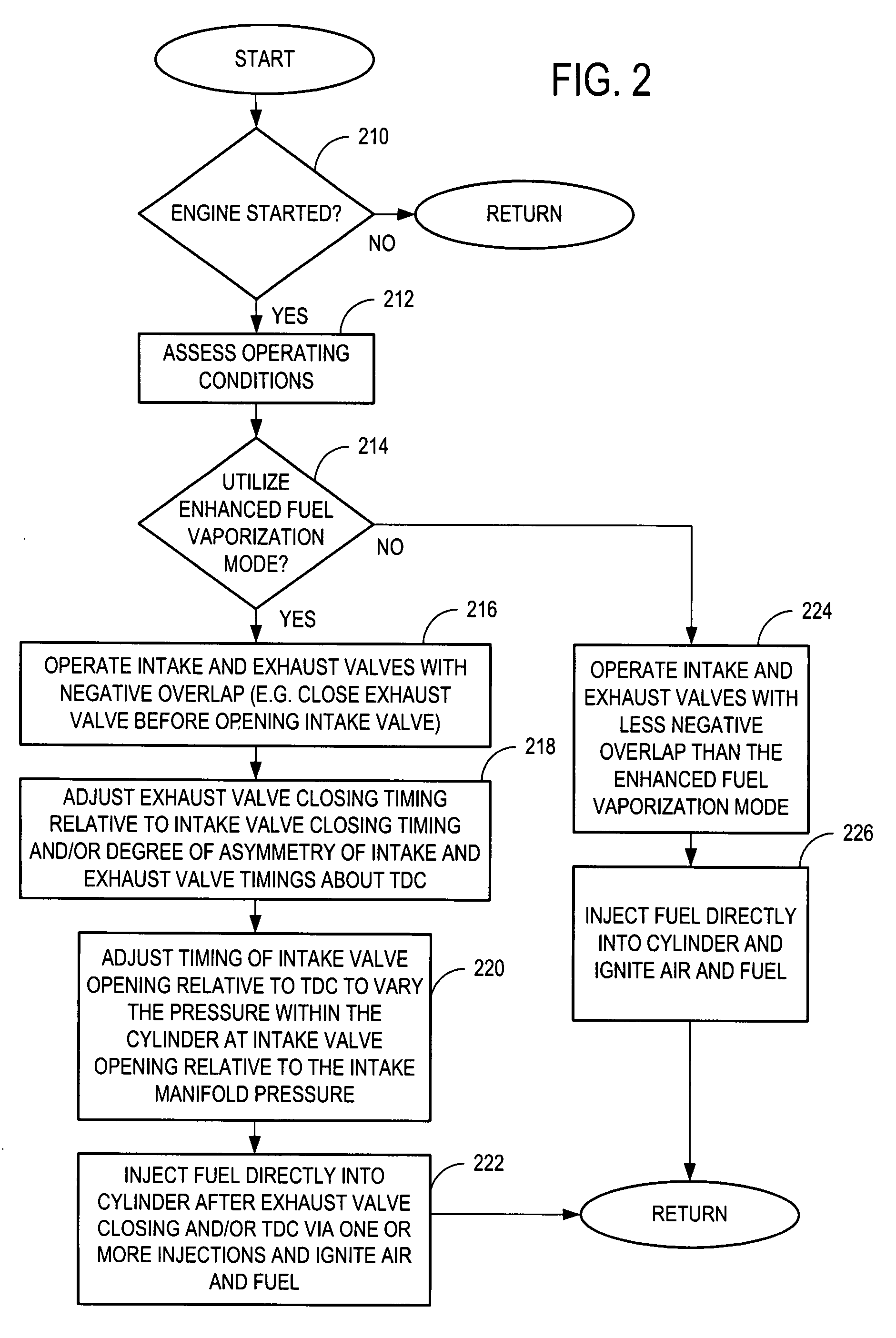
[0003]In this way, fuel vaporization may be improved by coordinating the timing of the directly injected fuel with intake valve opening while also utilizing negative valve overlap between the intake and exhaust valves to generate reduced pressures within the cylinder. These reduced cylinder pressures can improve the vaporization rate of the directly injected fuel since the boiling temperature of the fuel is reduced at lower cylinder pressures. Furthermore, the rate of air entrainment into the cylinder at intake valve opening can be increased by reducing the pressure within the cylinder to below the pressure of the intake manifold, thereby improving mixing of the entrained air and with the directly injected fuel which can further increase the fuel vaporization rate. Thus, emissions produced after engine start-up can be reduced by improving fuel vaporization as described herein.

Problems solved by technology

For example, after start-up of the engine, the fuel system pressure may not yet have attained a pressure to cause sufficient atomization of the fuel within the combustion chamber, which may result in increased emissions.
Furthermore, lower engine temperatures after start-up can further reduce the vaporization rate of the directly injected fuel.

Method used


Image

  • Approach for improved fuel vaporization in a directly injected internal combustion engine
  • Approach for improved fuel vaporization in a directly injected internal combustion engine
  • Approach for improved fuel vaporization in a directly injected internal combustion engine

Examples


Embodiment Construction

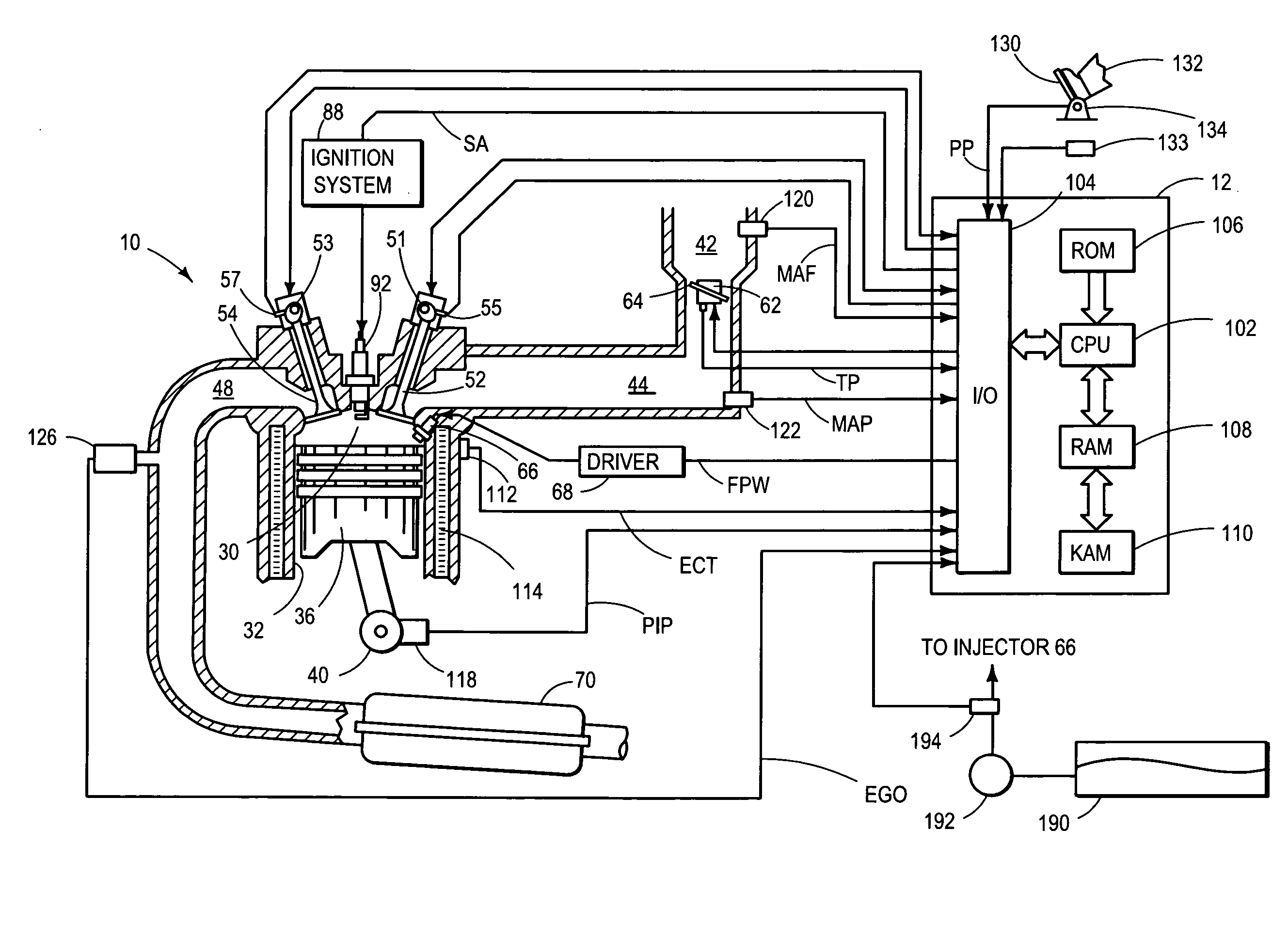
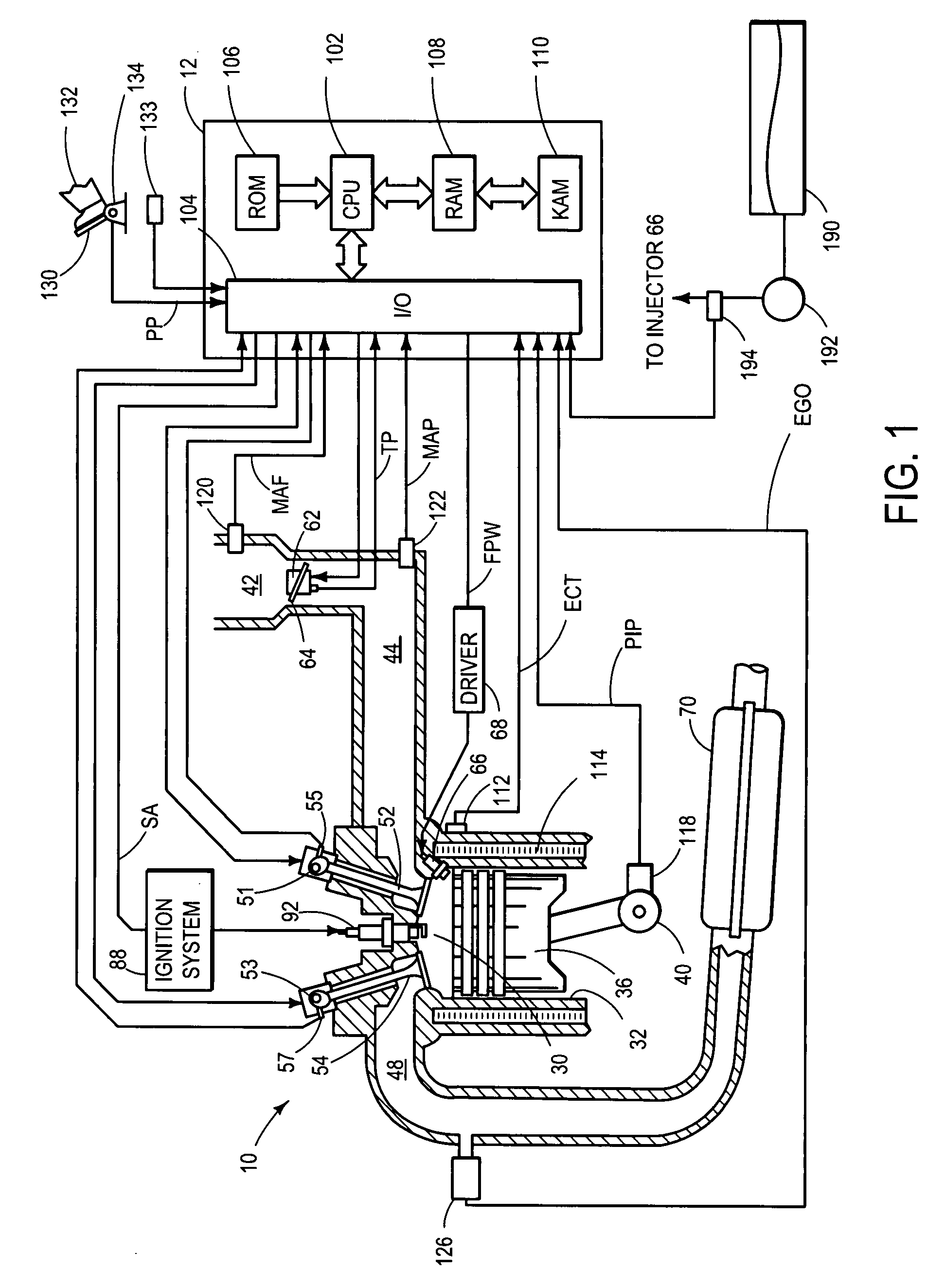
[0013]FIG. 1 shows a schematic depiction of an example cylinder 30 of an internal combustion engine 10 including an in-cylinder direct fuel injector 66. As one example, engine 10 can be configured as gasoline engine or a flexible fuel engine for a vehicle. For example, engine 10 can be configured to operate with a fuel including a mixture of gasoline and alcohol. Engine 10 may include multiple cylinders, one of which is shown in FIG. 1. It should be appreciated that each cylinder may similarly include its own set of intake / exhaust valves, fuel injector, spark plug, etc.

[0014]Engine 10 may be controlled by a control system including a controller 12. The engine control system including controller 12 can receive user input from a vehicle operator 132 via one or more user input devices. As one example, user 132 can utilize an accelerator pedal 130 to provide an input to the controller indicative of operator torque or speed request as identified by pedal position sensor 134. Further, the...


PUM


Abstract

A system and a method of facilitating fuel vaporization in a directly injected internal combustion engine are provided. As one example, vaporization may be improved by coordinating the timing of the directly injected fuel with intake valve opening while also utilizing negative valve overlap between the intake and exhaust valves to generate reduced pressures within the cylinder.

Description

BACKGROUND AND SUMMARY[0001]The inventors of the present disclosure have recognized that emissions produced by an engine shortly after start-up can constitute a large portion of the entire drive cycle emissions. Engines utilizing direct in-cylinder injectors can experience even greater emissions due to reduced fuel vaporization and atomization under certain conditions. For example, after start-up of the engine, the fuel system pressure may not yet have attained a pressure to cause sufficient atomization of the fuel within the combustion chamber, which may result in increased emissions. Furthermore, lower engine temperatures after start-up can further reduce the vaporization rate of the directly injected fuel. As yet another example, vaporization rate can vary with fuel composition. For example, blended fuels containing gasoline and alcohol may have lower vaporization rates than fuels containing only gasoline or lower concentrations of alcohol.[0002]As one approach, at least some of ...

Claims


Application Information

Patent Timeline
Patent Type & Authority Patents(United States)
IPC IPC(8): F02B17/00F02B31/00
CPCF02D13/0265F02D41/068F02D41/401F02B2075/125F02D41/402F02D2041/001F02D2041/389Y02T10/44Y02T10/123Y02T10/18Y02T10/12Y02T10/40
Inventor YI, JIANWEN JAMESIYER, CLAUDIA OLIVIATING, FOOCHERNDAVIS, GEORGE CARVER
Owner FORD GLOBAL TECH LLC
Learn More