Method and device for removing hair

a hair removal and hair technology, applied in the field of aesthetic care, can solve the problems of ineffective acoustic wave coupling, prior art failure to provide hair removal methods, and inability to teach how to effectively couple acoustic waves, so as to improve acoustic coupling and minimize the vibration of hair

Active Publication Date: 2011-08-09
APPLISONIX
View PDF31 Cites 5 Cited by
  • Summary
  • Abstract
  • Description
  • Claims
  • Application Information

AI Technical Summary

Benefits of technology

[0028]Furthermore, the prior art fails to provide a hair removal method in which the transmission of acoustic waves through the hair shaft is improved by minimizing vibration of the hair haft.
[0058]According to still another features in the described preferred embodiments at least one of: a frequency, a power density and duration of transmission of the acoustic waves is select so as to minimize longitudinal vibrations of the hair.

Problems solved by technology

The prior art fails to provide a hair removal method in which the transmission of acoustic waves through the hair shaft generate sufficient heat to destroy the hair root.
Although the prior art recites the use of acoustic waves for removal of unwanted hair, the prior art fails to provide a range of frequencies which is suitable to effect a transmission of acoustic waves through the hair shaft into the follicle.
Additionally the prior art fails to teach how to effectively couple the acoustic waves and the hair shaft so as to allow the transmission of the acoustic waves through the hair shaft.
Furthermore, the prior art fails to provide a hair removal method in which the transmission of acoustic waves through the hair shaft is improved by minimizing vibration of the hair haft.

Method used


Image

  • Method and device for removing hair
  • Method and device for removing hair
  • Method and device for removing hair

Examples


examples

[0167]Reference is now made to the following examples, which together with the above descriptions illustrate the invention in a non limiting fashion.

Computational Model

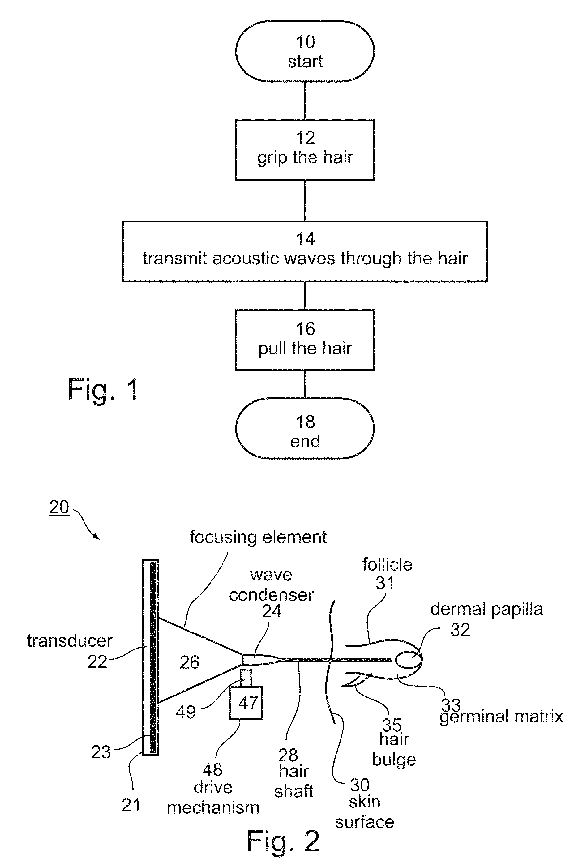
[0168]FIG. 8 is a schematic illustration of a simplified model of the geometry of the hair, which include three well distinguished regions: (i) the hair shaft above and below the skin surface, (ii) the hair bulb which comprises the dermal papilla and the germinal matrix, and (iii) the hair bulge, which is a part of the follicle and located near the hair shaft between the skin surface and the hair bulb. The hair shaft has a substantially smooth and extended structure and is located within the air, or the soft tissues which have distinctly different acoustic impedance. The hair shaft presents a good system for guiding an acoustic energy from the top end to the hair bulge and the entry point into the hair bulb.

[0169]The geometry of the hair bulb and hair bulge considerably differs from the geometry of the hair shaft. Mul...

experiment 1

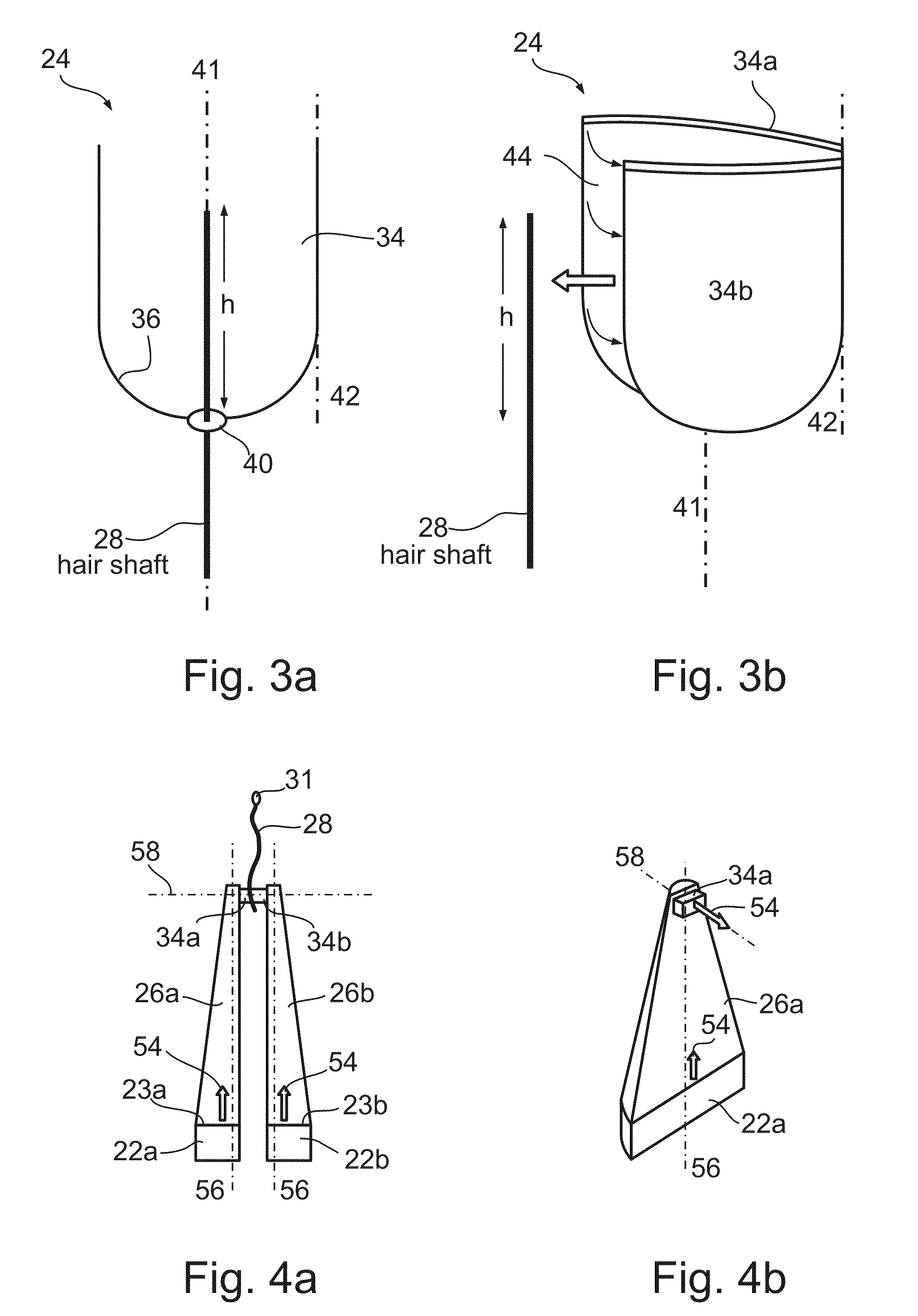
[0177]A prototype wave condenser was built in accordance with a preferred embodiment of the present invention. The wave condenser was manufactured with a pore which was filled with ultrasound transmission gel. The diameter of the wave condenser was 8 mm and the dimensions of the pore were 1 mm in diameter and 5 mm in length.

[0178]A few human hair shafts were introduced into the condenser. An ultrasound transducer was assembled directly on the condenser, without intermediate focusing element. The ultrasound transducer was operated for about 0.1 second at a frequency of 1005 kHz and a power density of about 5.2 watts / cm2 on its surface.

[0179]FIG. 9 is an infrared image of the treated hair shafts. Also shown in FIG. 9 is an image of the wave condenser. As shown in FIG. 9, the acoustic waves successfully heated the hair shafts with the hot point at the distal end of the hair shaft acquiring a temperature of 142° C.

experiment 2

[0180]Four human hair shafts were introduced into the wave condenser of Experiment 1. For each hair shaft, a different coupling length h was defined by a different insertion depth of the hair shaft into the wave condenser. The following coupling lengths were examined, h=2 mm, h=4 mm, h=6 mm and h=8 mm. The ultrasound frequency was 817 kHz, and the power density at the surface of the ultrasound transducer was set at two values: a lower density of about 1.2 watts / cm2 and higher density of about 2.5 watts / cm2.

[0181]FIG. 10 is a graph showing the temperature of the hair shafts as a function of the coupling length. As shown in FIG. 10, a close to linear increment of the hair shaft temperature with h was observed. This result is in agreement with the above model, because larger values of the coupling length correspond to higher levels of wave penetration into the hair shaft thereby to larger ultrasound energy propagation within the hair shaft.


PUM


Abstract

A method of treating unwanted hair is disclosed. The method comprises: transmitting acoustic waves through the hair so as to generate heat at a follicle, a dermal papilla, a hair bulge and / or a germinal matrix of the hair. The heat itself is sufficient to damage or destroy the follicle, the dermal papilla, the hair bulge and / or the germinal matrix.

Description

RELATED APPLICATIONS[0001]This application is a National Phase Application of PCT Patent Application No. PCT / IL2005 / 000210 having International Filing Date of Feb. 20, 2005, which claims the benefit of U.S. Provisional Patent Application No. 60 / 546,956 filed on Feb. 24, 2004. The contents of the above Applications are all incorporated herein by reference.FIELD AND BACKGROUND OF THE INVENTION[0002]The present invention relates to aesthetic care and, more particularly, to a method and device for removing hair.[0003]A hair is composed of a protein named keratin arranged in three layers, termed the outer cuticle; the middle cortex and the central medulla. Hair grows from a follicle, which is a small cup-shaped pit buried under the skin. The walls of the follicle form the outer root sheath of the hair. The base of the hair follicle, called the dermal papilla, is fed by the bloodstream which carries nourishment (e.g., nutrients and oxygen) to produce new hair and removes waste materials f...

Claims


Application Information

Patent Timeline
Patent Type & Authority Patents(United States)
IPC IPC(8): A61B18/00A61B18/04A61B17/00A61N7/00
CPCA45D26/00A45D26/0009A61N7/00A45D2200/207A61B2017/00752A45D2026/008A61B18/12
Inventor BARZILAY, AMIRGOREN, ALONDAYAN, ABRAHAMFURMAN, VLADIMIRGUTERMAN, ASSAFNIV, YEHUDA
Owner APPLISONIX
Why Eureka
Try Eureka