Internal injection betatron

a betatron and injection technology, applied in the field of formation evaluation methods and devices, can solve the problems of strict control, long half life of most sources, and source radiation hazards

Active Publication Date: 2011-08-09
SCHLUMBERGER TECH CORP
View PDF3 Cites 9 Cited by
  • Summary
  • Abstract
  • Description
  • Claims
  • Application Information

AI Technical Summary

Benefits of technology

[0022]Operation of this betatron can include forming a first magnetic flux of a first polarity that passes through the guide magnet, the electron acceleration passageway and the core and then returns through the return yokes, and a second magnetic flux of either the first polarity or of an opposing second polarity that passes through the core and returns through the guide magnet gap and the electron acceleration passageway. At the beginning of each cycle, a high voltage pulse (typically a few kV) is applied to the injector and causes electrons to be injected into the electron acceleration passageway. To achieve fast contraction without compromising the maximum energy the core is a hybrid core having a perimeter portion made of fast ferrite surrounding a slower, but high saturation flux density material. During the first time period most of the flux needed to reduce the radius of electron orbits flows through the fast ferrite. After this first time duration, the fast ferrite perimeter of the core magnetically saturates and the second magnetic flux then flows through the internal portion of the core and in combination with the first magnetic flux accelerates the electrons. The polarity of the second magnetic flux is reversed when the electrons approach a maximum velocity thereby expanding the electron orbit and causing the electrons to impact a target generating x-rays.

Problems solved by technology

These sources pose a radiation hazard and require strict controls to prevent accidental exposure or intentional misuse.
In addition, most sources have a long half life and disposal is a significant issue.
Satisfying the betatron condition does not insure the machine will work.
Charge trapping, injecting electrons into the betatron orbit at the optimal point of time, is another challenging operation.
(1) If the electron injector is located in the gap between pole faces, the gap height must be larger than the dimension of the injector perpendicular to the pole faces. In order to maintain a reasonable beam aperture, the width of the pole faces cannot be reduced too much either. Thus, the burden of the size reduction falls mostly on the core, resulting in significantly lower beam energy.
(2) If the electron injector is located in the gap between the pole faces, one must, within a time period comparable to the orbit period of electrons, alter the injected electrons trajectories such that they do not hit the injector. Those electrons whose trajectories do not intercept either the injector structure or the vacuum chamber walls are said to be trapped. Only trapped electrons may be accelerated to full energy and caused to impinge on the target and produce radiation. Due to the nature of the charge trapping mechanism, the probability of trapping any charge in a 3 inch machine is almost nil unless the modulation frequency of the main drive is increased to about 24 kHz (triple that of a 4.5 inch machine) and the injection energy is reduced to about 2.5 kV (½ that of the 4.5 inch machine). Even then, the prospect of trapping a charge comparable to that trapped in a 4.5 inch machine is poor.
(3) A higher flux density is required to confine the same energy electrons to a smaller radius. A higher flux density and modulation frequency results in a higher power loss in a three inch betatron, even though it has a smaller volume than a 4.5 inch betatron.
The energy of the electrons can be limited by material properties and available power whereas the former is mainly an issue of the amount of charge trapped, which is in turn affected by strength of the focusing forces, the space charge forces, and the efficiency of the charge trapping mechanism.
The trapped charge is always less than the maximum allowed charge because the mechanism isn't 100% efficient.
For example, the conventional approach uses an external injection scheme which provides for inefficient trapping in a small betatron.
In a small circular electron accelerator such as a betatron, injection of elections into the acceleration cavity poses a significant challenge.

Method used


Image

  • Internal injection betatron
  • Internal injection betatron
  • Internal injection betatron

Examples


Embodiment Construction

[0051]The particulars shown herein are by way of example and for purposes of illustrative discussion of the embodiments of the present invention only and are presented in the cause of providing what is believed to be the most useful and readily understood description of the principles and conceptual aspects of the present invention. In this regard, no attempt is made to show structural details of the present invention in more detail than is necessary for the fundamental understanding of the present invention, the description taken with the drawings making apparent to those skilled in the art how the several forms of the present invention may be embodied in practice. Further, like reference numbers and designations in the various drawings indicated like elements.

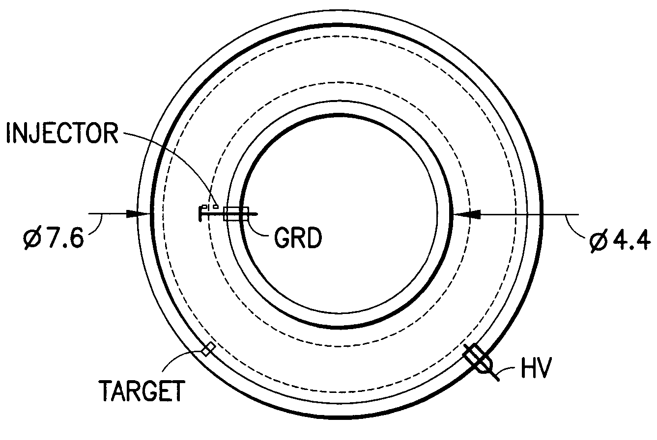
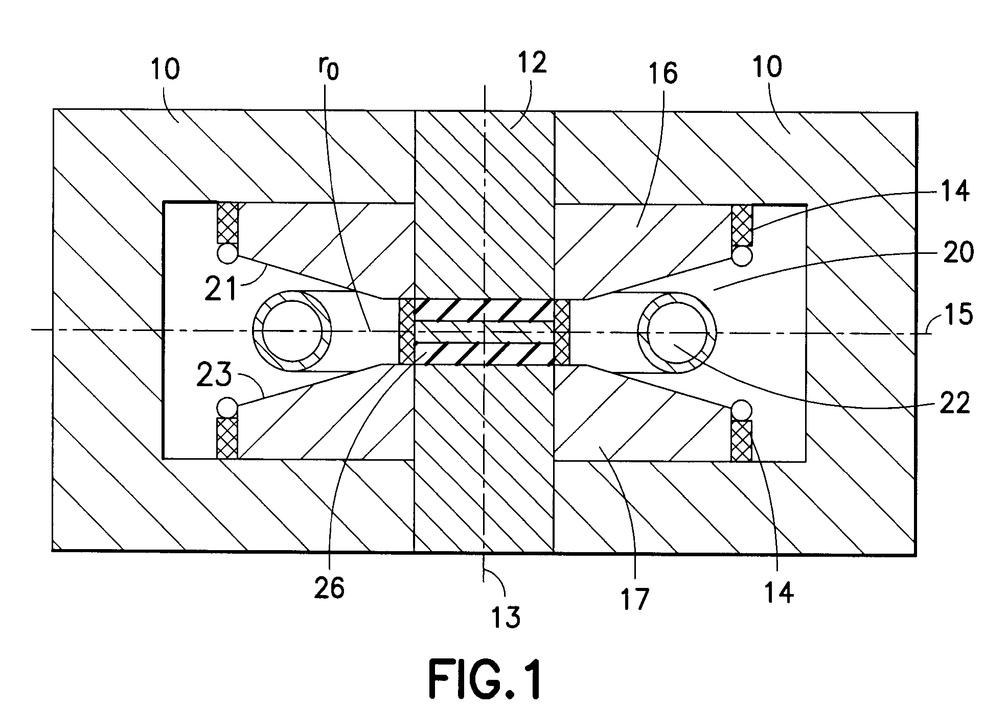
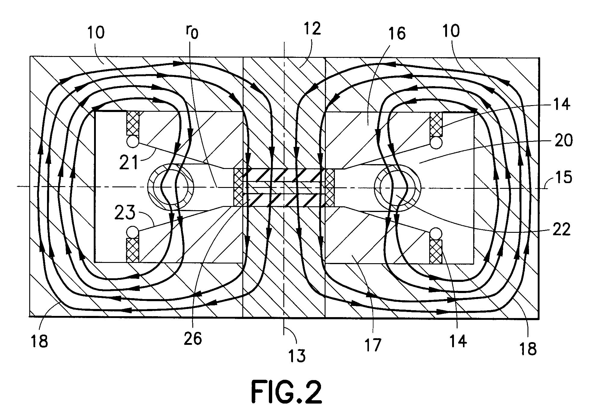
[0052]According to embodiments of the invention, the invention includes a betatron magnet having at least one electron injector positioned approximate an inside of a radius of the betatron orbit, the betatron magnet comprisin...


PUM

PropertyMeasurementUnit
widthaaaaaaaaaa
widthaaaaaaaaaa
diametersaaaaaaaaaa

Abstract

A betatron magnet having at least one electron injector positioned approximate an inside of a radius of a betatron orbit, the betatron magnet further includes a first guide magnet having a first pole face and a second guide magnet having a second pole face. Both the first and the second guide magnet have a centrally disposed aperture and the first pole face is separated from the second pole face by a guide magnet gap. A core is disposed within the centrally disposed apertures in an abutting relationship with both guide magnets. The core has at least one core gap. A drive coil is wound around both guide magnet pole faces. An orbit control coil has a core portion wound around the core gap and a field portion wound around the guide magnet pole faces. The core portion and the field portion are connected but in opposite polarity.

Description

CROSS REFERENCE TO RELATED APPLICATION(S)[0001]This patent application claims priority from U.S. patent application Ser. No. 11 / 957,178 filed Dec. 14, 2007,incorporated by reference herein in its entirety.BACKGROUND OF THE INVENTION[0002]1. Field of the Invention[0003]This invention generally relates to methods and devices of formation evaluation using a switchable source, in particular, injecting electrons near the inner radius of a vacuum donut of a compact betatron electron accelerator.[0004]2. Background of the Invention[0005]Known methods and devices of formation evaluation are typically used in oil well bore hole logging applications, such applications are understood as a process where properties of earth strata as a function of depth in the bore hole are measured. For example, geologists reviewing the logging data can determine the depths at which oil containing formations are most likely located. One important piece of the logging data is the density of the earth formation. ...

Claims


Application Information

Patent Timeline
Patent Type & Authority Patents(United States)
IPC IPC(8): H05H11/00H01F7/08H01J35/00H01F7/00
CPCH01J35/00H05G2/00H05H11/00
Inventor CHEN, FELIX K.
Owner SCHLUMBERGER TECH CORP
Why Eureka
Try Eureka